support@comsol.com
RF Module Updates
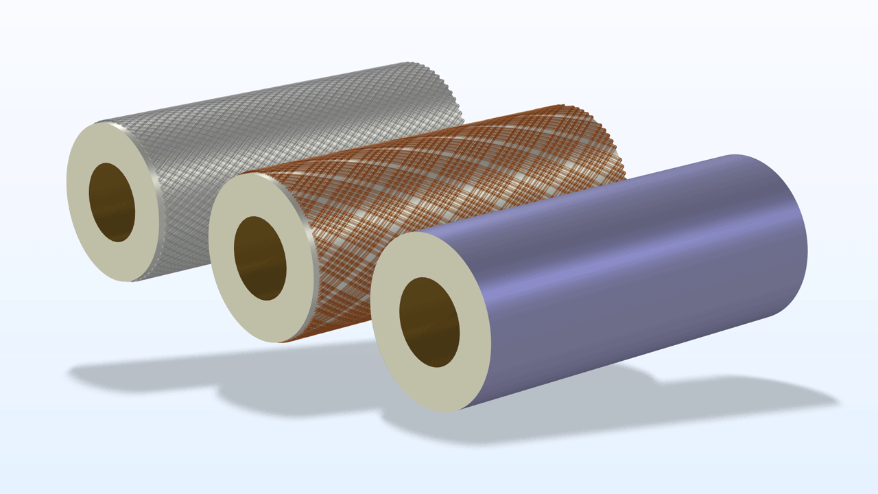
For users of the RF Module, COMSOL Multiphysics® version 6.2 introduces a new feature for efficient simulation of braided cable shields, a new material model for PCB substrates, and performance improvements to the Electromagnetic Waves, Boundary Elements interface. Learn more about these updates below.
New Boundary Condition Added to the Electromagnetic Waves, Frequency Domain Interface
A new Cable Shield feature has been integrated into the Electromagnetic Waves, Frequency Domain interface. This feature enables efficient simulation of intricate shields, such as braided or perforated types, using a streamlined boundary condition that reduces computational demands.
Performance Improvements for the Electromagnetic Waves, Boundary Elements Interface
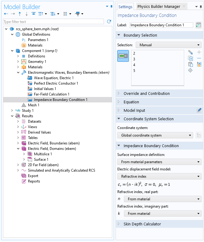
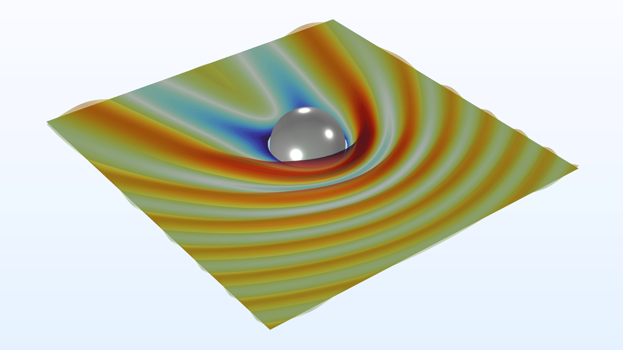
In the settings for the Electromagnetic Waves, Boundary Elements interface, it is now possible to select symmetry planes to reduce computation time. The symmetry settings also control the far-field calculations and physics-controlled meshing. The new RCS of a Metallic Sphere Using the Boundary Element Method (RF) model showcases this functionality.
Furthermore, boundary element method (BEM) simulations on clusters are up to 2.5 times faster than in previous versions. If you also include the effect of reducing the model using a symmetry plane, then simulation times are up to 4 times faster. Additionally, the load and memory balancing for BEM models running on clusters has been significantly improved.
New and Improved Features in the Electromagnetic Waves, Boundary Elements Interface
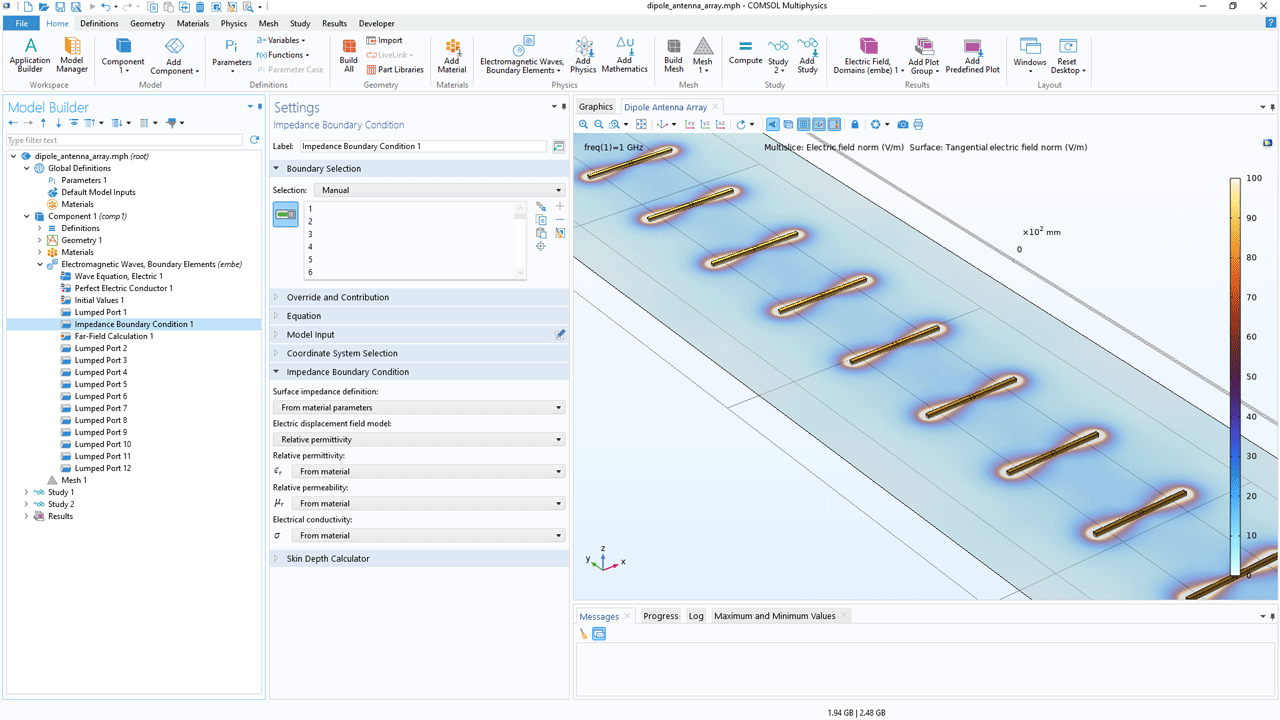
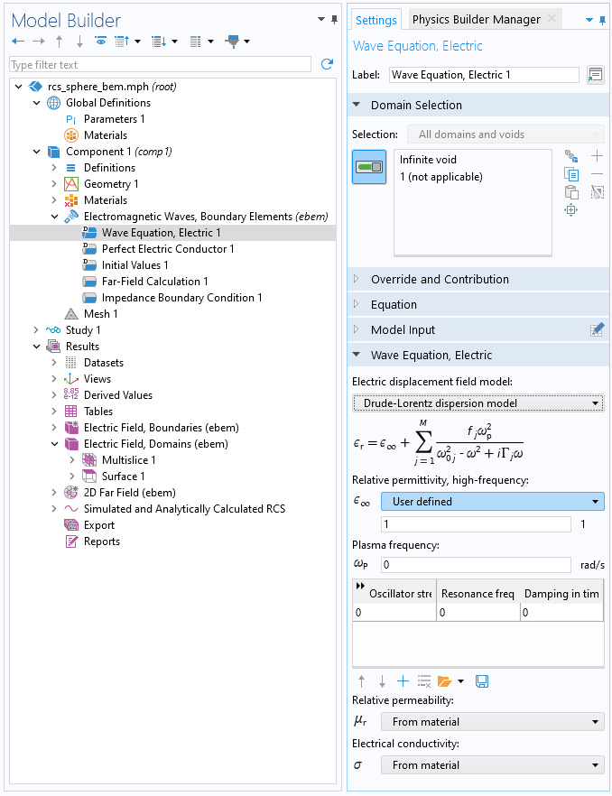
The Impedance Boundary Condition and the Layered Impedance Boundary Condition have been added to the Electromagnetic Waves, Boundary Elements interface. These boundary conditions handle metallic exterior domains and metallic exterior domains covered by a layered structure, respectively. You can view this new addition in the Modeling of Dipole Antenna Array Using the Boundary Element Method tutorial model.
The default feature, Wave Equation, Electric, now includes all standard Electric displacement field model options, such as Relative permittivity, Refractive index, Dielectric loss, etc. This simplifies the use of different materials, supporting different material models.
New Electric Displacement Field Model
For the Electromagnetic Waves, Frequency Domain interface and Electromagnetic Waves, Boundary Elements interface, a new electric field displacement model, Wideband Debye model, is available in the Wave Equation, Electric feature. This model can be used to accurately describe losses and dispersive effects in PCB substrates.
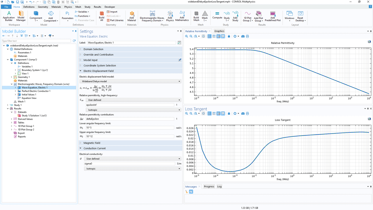
Electrical Conductivity Added to Drude–Lorentz and Debye Dispersion Models
The Drude–Lorentz and the Debye dispersion models now have additional flexibility, allowing separate input of the electrical conductivity.
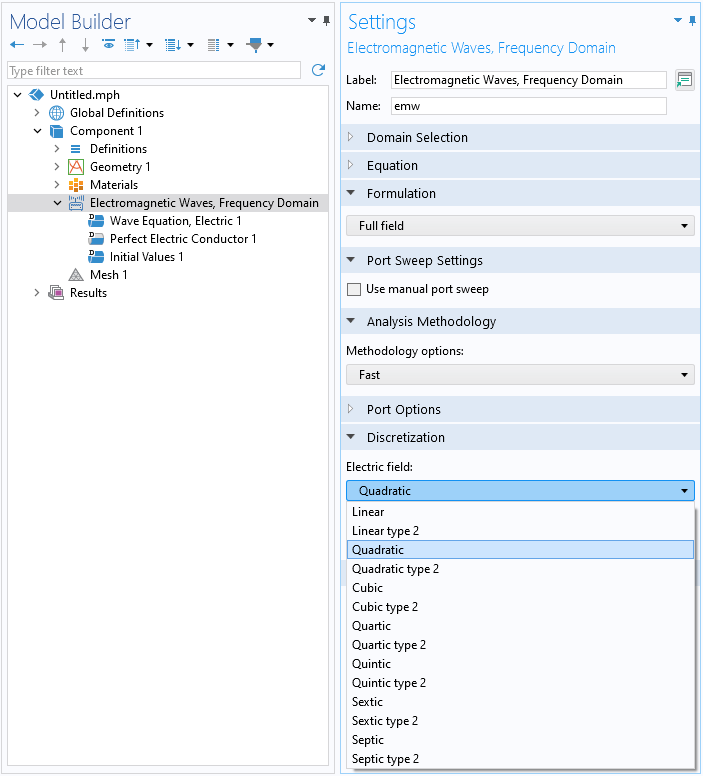
Higher-Order Elements
In this version, up to seventh-order curl elements can now be used in the Electromagnetic Waves, Frequency Domain interface and the Electromagnetic Waves, Transient interface.
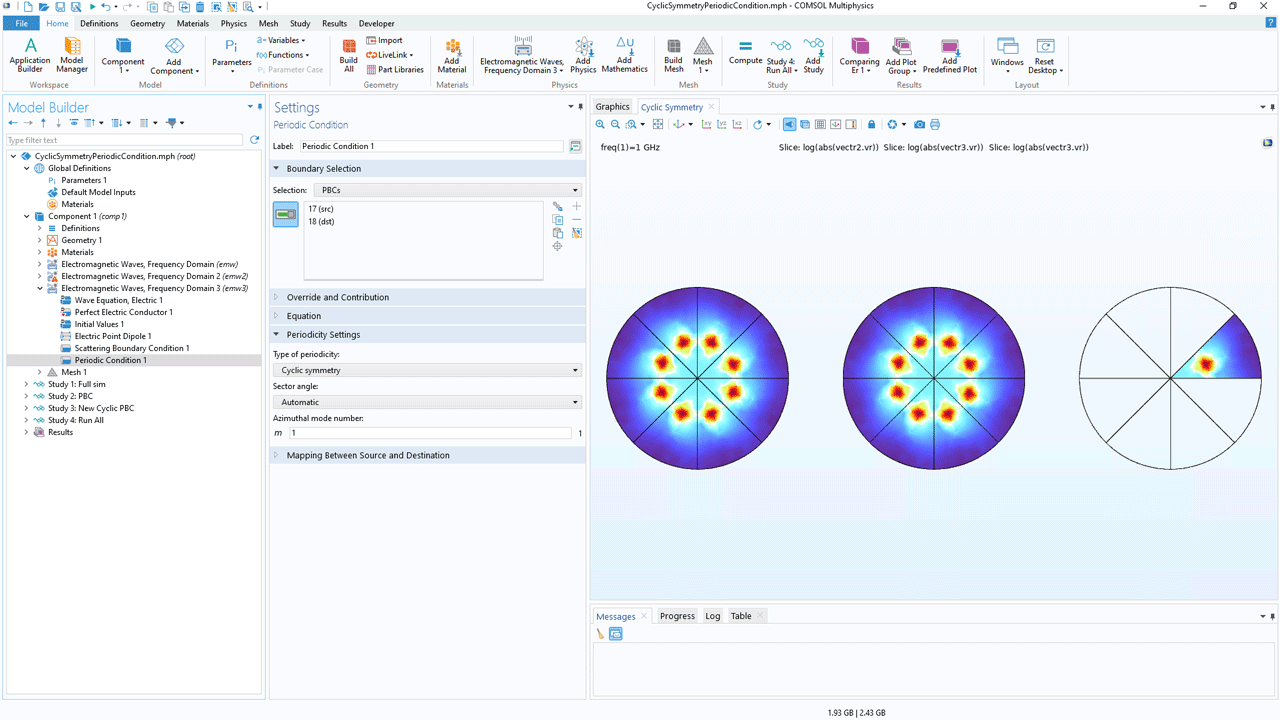
Cyclic Symmetry for Periodic Condition
Cyclic symmetry has been added as a periodicity option to the Periodic Condition feature. This option provides the ability to perform simulations of one sector of a full, cyclically symmetric model as opposed to the full model, reducing computation time.
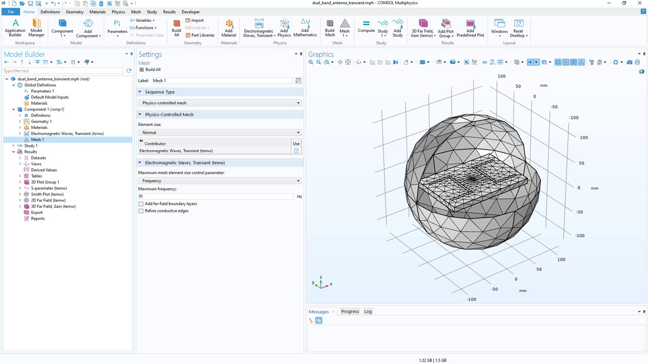
Time-Domain Physics-Controlled Mesh
The time-domain interfaces, Electromagnetic Waves, Transient and Electromagnetic Waves, Time Explicit, now provide physics-controlled mesh suggestions based on the frequency or wavelength content of a simulation. The following tutorial models showcase this new update:
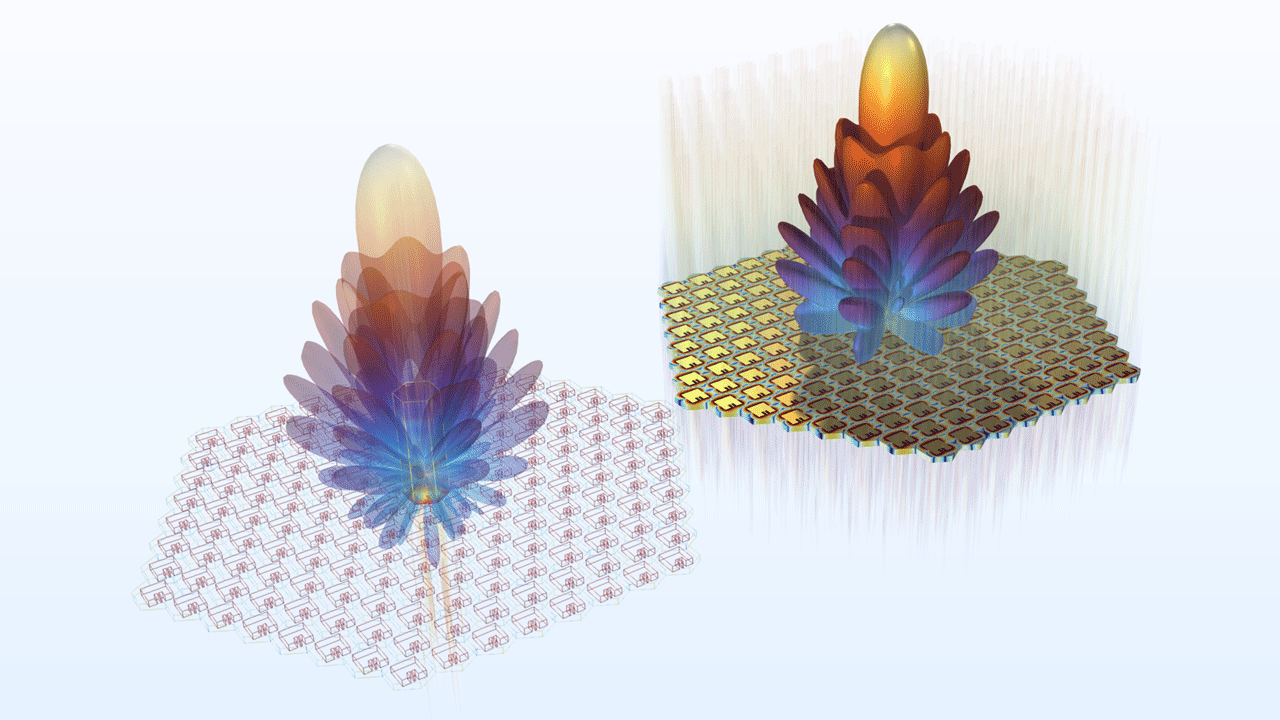
Hexagonal Uniform Array Factor
The hexagonal uniform array factor quickly estimates the far-field pattern of antenna arrays on a triangular grid. In version 6.2, the hexagonal antenna arrays provide lower sidelobes, more robust performance with better resolution, lower spatial noise, and wider coverage.
Instantaneous Norm Variables for Vector Quantities
There are new variables that can be added to the form phys.normXi = sqrt(real(Xx)^2+real(Xy)^2+real(Xz)^2), where phys is a placeholder for any physics tag, such as ewfd, and X is a placeholder for a physical quantity, such as an electric field (E), magnetic field (H), etc. These variables are especially useful when visualizing time-harmonic vector waves.
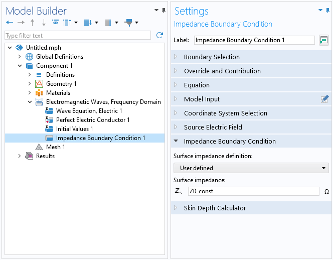
User-Defined Surface Impedance
In the Impedance Boundary Condition feature and the Layered Impedance Boundary Condition feature, it is now possible to directly enter a surface impedance. Previously, the surface impedance was calculated indirectly from the material properties defined on the boundary or in the feature settings. This simplifies the modeling process for problems where it is less relevant to use actual materials for modeling the exterior domain.
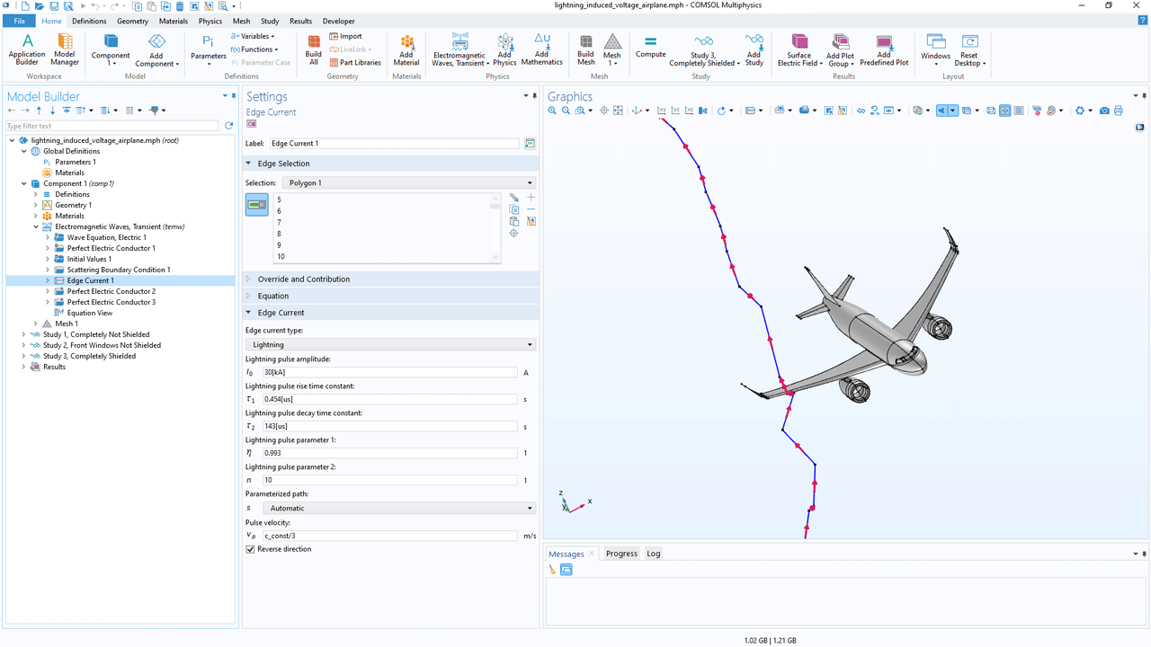
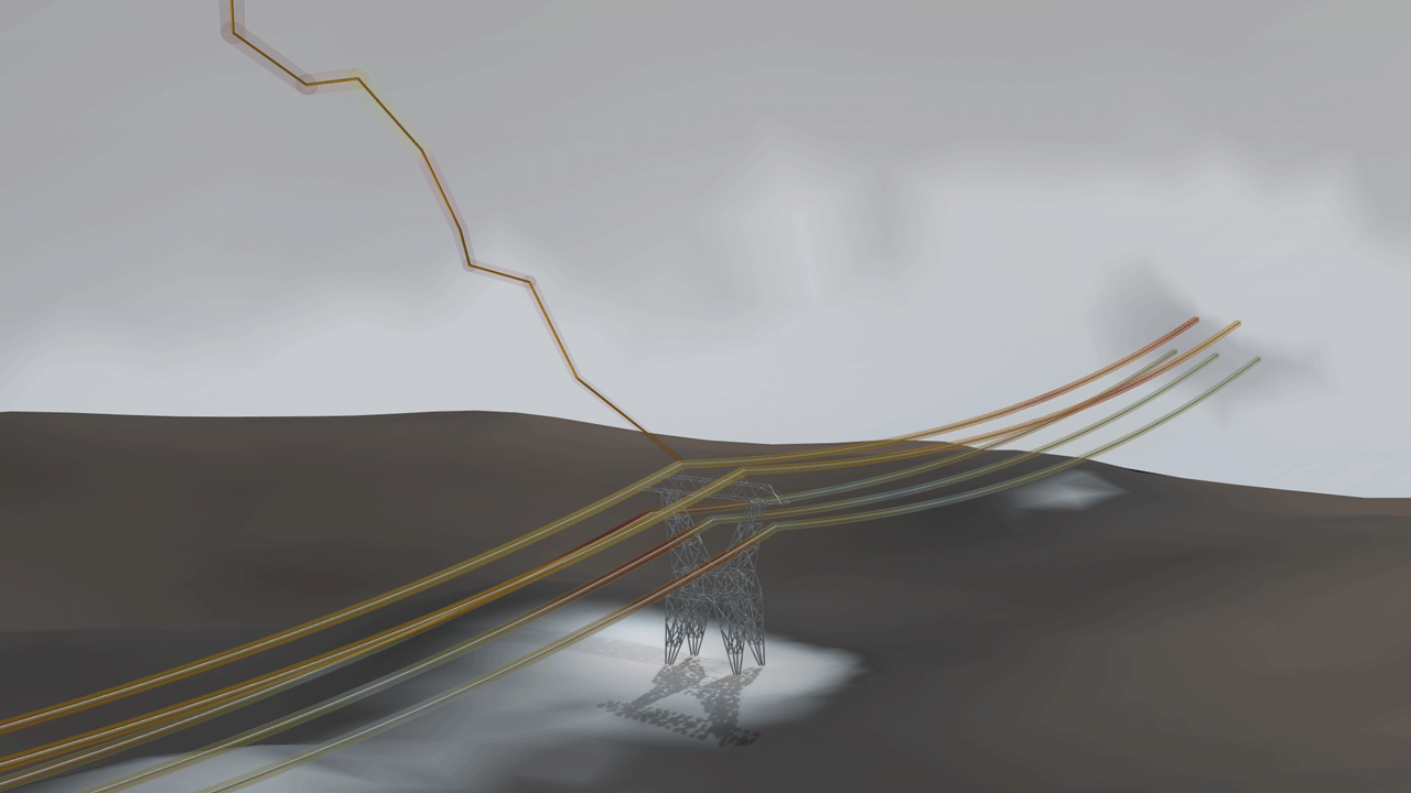
Automatic Path Parameterization for Lightning and Electrostatic Discharge (ESD) Applications
The Edge Current feature in the Electromagnetic Waves, Transient interface can adaptively determine a parameterized path based on the selected geometry's unique shape. This enhancement simplifies the modeling process for lightning and ESD applications. View this feature in the following tutorial models:
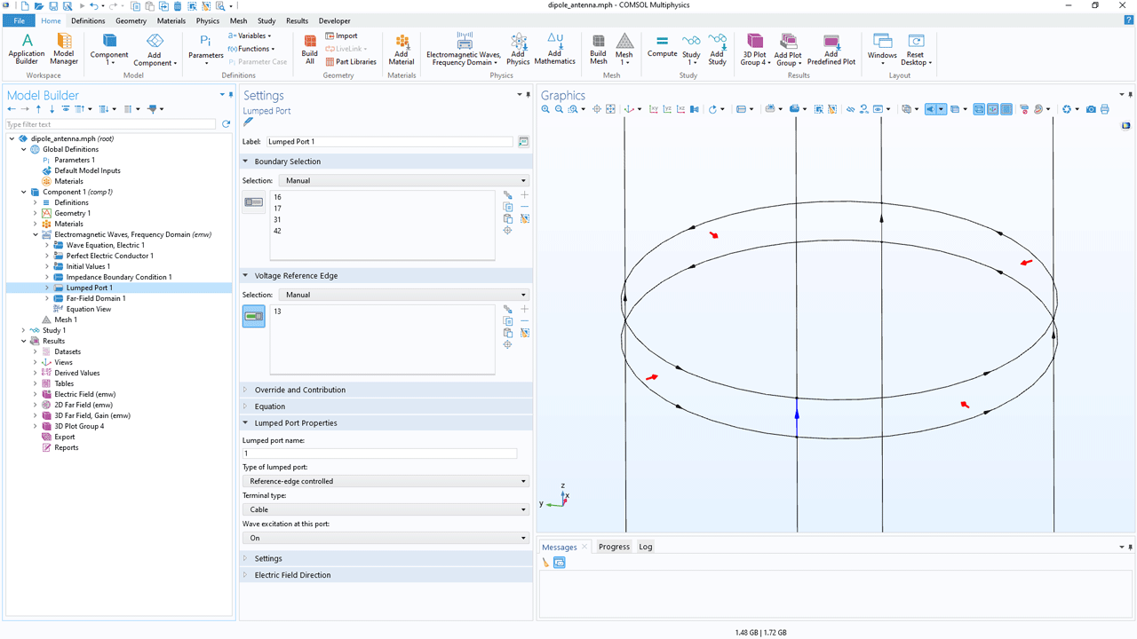
Reference-Edge Controlled Lumped Port Type
The Lumped Port feature now includes a Reference-edge controlled type. This option can be used to designate extra edge selections, ensuring the proper direction of voltage flow between two conductive boundaries where a lumped port is positioned.
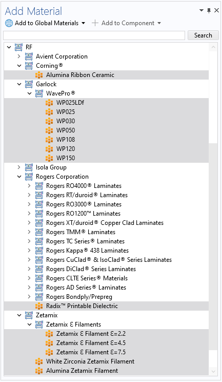
Enhanced Material Options for Millimeter-Wave Applications
The RF material library has been expanded to include:
- Alumina Ribbon Ceramic from Corning Incorporated
- WavePro® WP025LDf, WavePro® WP025, WavePro® WP030, WavePro® WP050, WavePro® WP108, WavePro® WP120, and WavePro® WP150 from Garlock
- Radix™ Printable Dielectric by Rogers Corporation
- Zetamix Ɛ Filaments, White Zirconia Zetamix Filament, and Alumina Zetamix Filament, sourced from Zetamix
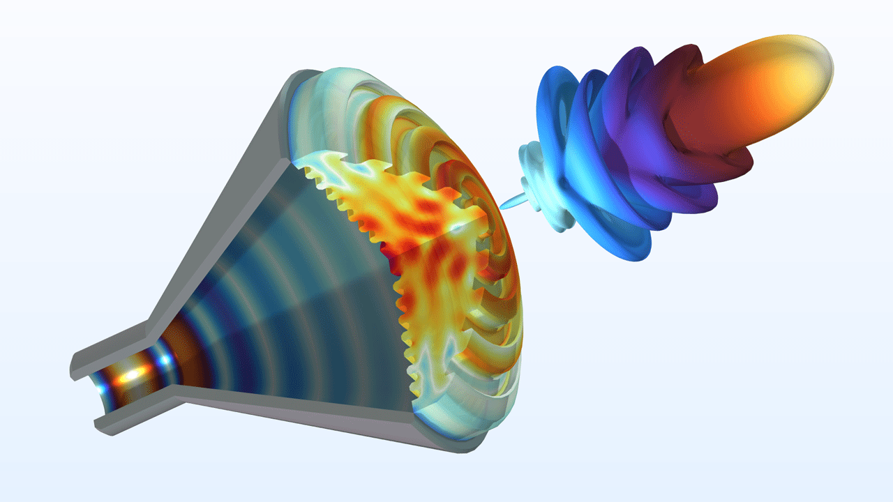
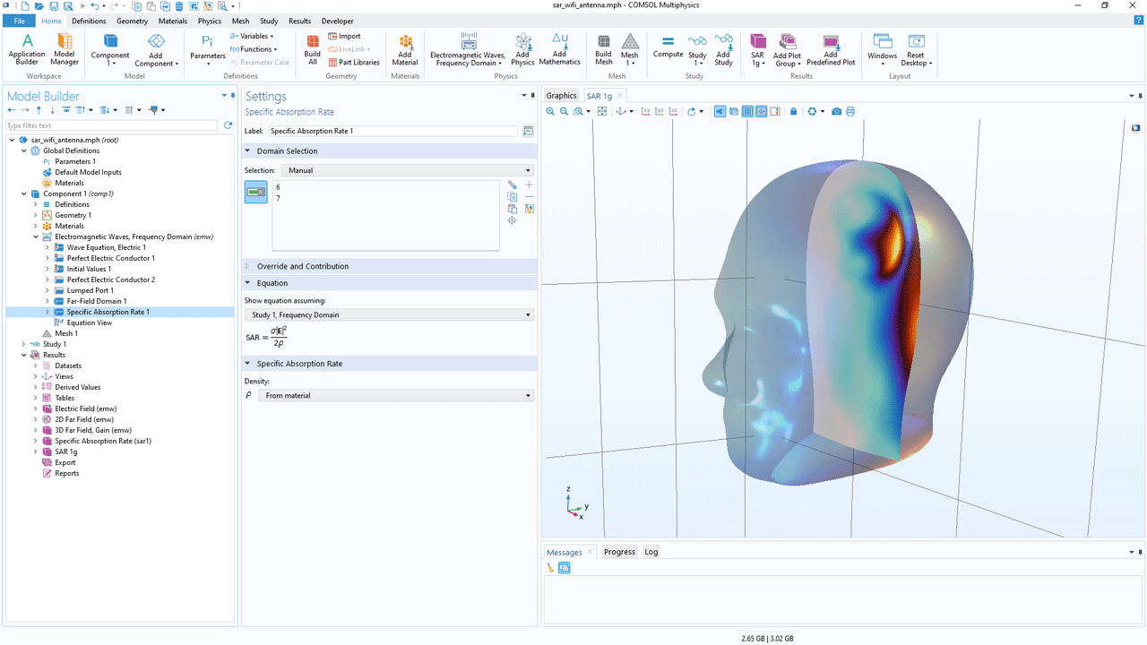
Assessment of Specific Absorption Rate (SAR) for 1-g and 10-g Mass
In the Electromagnetic Waves, Frequency Domain interface, the Specific Absorption Rate feature has been extended for modeling of electromagnetic interactions with biological tissue. After computation, this feature provides predefined SAR results variables for tissue exposure. These variables represent SAR values for 1 g and 10 g of tissue mass and are commonly employed in industrial applications to measure radiation exposure levels. The SAR of a Human Head Next to a Wi-Fi Antenna model showcases this new update.
New Tutorial Models
COMSOL Multiphysics® version 6.2 brings the following new tutorial models to the RF Module.
RCS of a Metallic Sphere Using the Boundary Element Method
Application Library Title:
rcs_sphere_bem
Download from the Application Gallery
Lightning Surge on a Power Transmission Tower
Application Library Title:
lightning_surge_tower
Download from the Application Gallery
Lightning Surge Analysis of an Offshore Wind Farm
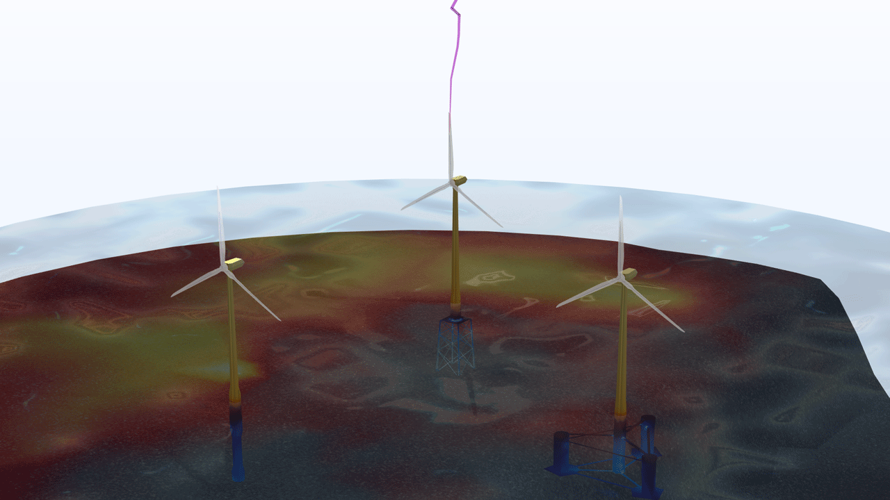
Application Library Title:
lightning_surge_wind_farm
Download from the Application Gallery
Modeling of a Dipole Antenna Array Using the Boundary Element Method
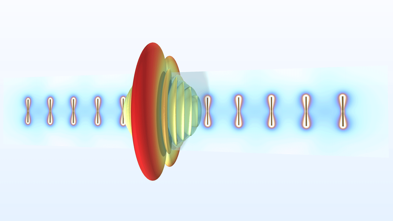
Application Library Title:
dipole_antenna_array
Download from the Application Gallery