

At Boeing, innovation comes in the form of modern aircraft such as the 787 Dreamliner, whose body is made up of over 50% carbon fiber composite. While incredibly lightweight and strong, such aircraft composites are not inherently conductive, thus requiring additional protective coatings to mitigate lightning strike damage. Here, we describe how multiphysics simulation is used to evaluate thermal stress and displacement in the protective coatings that undergo temperature fluctuations associated with the typical flight cycle.
High-Performance Coatings for Aircraft Composites
Advanced composites are used extensively throughout the Boeing 787 Dreamliner, as shown in the diagram below. Also known as carbon fiber reinforced plastic (CFRP), the composites are formed from a lightweight polymer binder with dispersed carbon fiber filler to produce materials with high strength-to-weight ratios. Many wing components, for example, are made of CFRP, ensuring that they can support the load imposed during flight while minimizing their overall contribution to the weight of an aircraft.
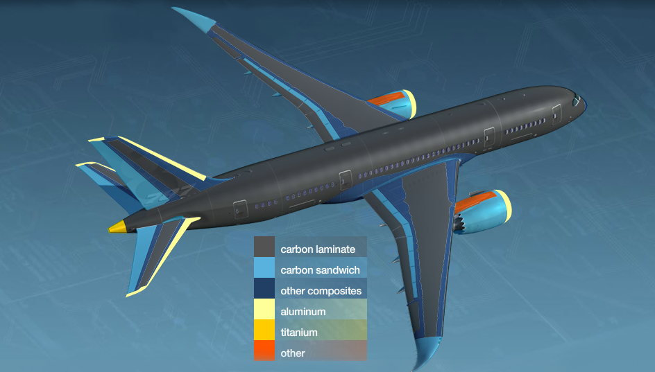
Advanced composites are used throughout the body of the Boeing 787. Copyright © Boeing.
Despite their remarkable strength and light weight, CFRPs are generally not conductive like their aluminum counterparts, thus making them susceptible to lightning strike damage. Therefore, electrically conductive expanded metal foil (EMF) is added to the composite structure layup, shown in the figure below, to dissipate the high current and heat generated by a lightning strike.
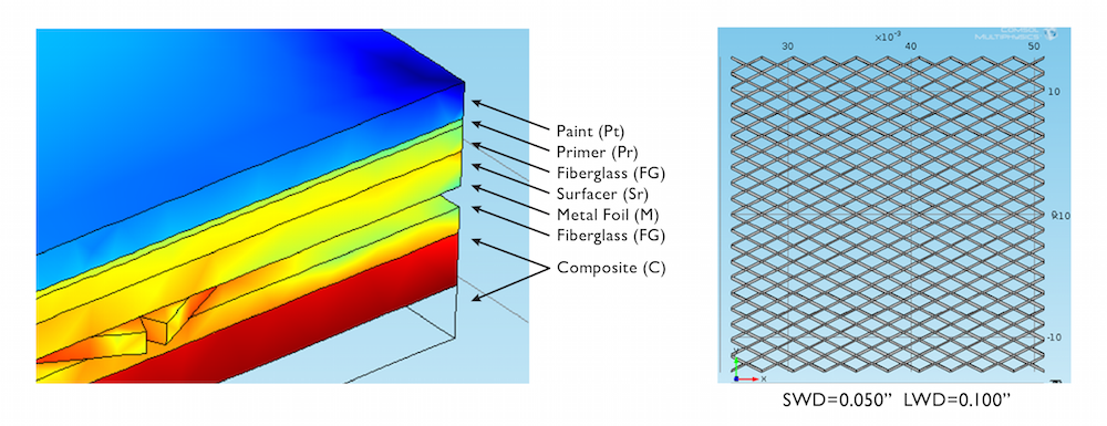
The composite structure layup shown at left consists of an expanded metal foil layer shown at right. This figure is a screenshot from the COMSOL Multiphysics® software model featured in this blog post. Copyright © Boeing.
The figure also shows the additional coatings on top of the EMF, which are in place to protect it from moisture and environmental species that cause corrosion. Corrosive damage to the EMF could result in lower conductivity, thereby reducing its ability to protect aircraft structures from lightning strike damage. Temperature variations due to the ground-to-air flight cycle can, however, lead to the formation of cracks in the surface protection scheme, reducing its effectiveness.
Thermal Stress, Displacement, and Crack Formation
During takeoff and landing, aircraft structures are subjected to cooling and heating, respectively. Thermal stress manifests as the expansion and compression — or ultimately the displacement — of adjacent layers throughout the depth of the composite structure. Although a single round-trip is not likely to pose a significant risk, over time, each layer of the composite structure contributes to fatigue damage buildup. Repetitive thermal stress results in cumulative strain and higher displacements, which are, in turn, associated with an increased risk of crack formation. The stresses in a material depend on its mechanical properties quantified by measurable attributes such as yield strength, Young’s modulus, and Poisson’s ratio.
Simulating Thermal Stress and the Ground-to-Air Flight Cycle
By taking the thermal and mechanical properties of materials into account, it is possible to use simulation to design and optimize a surface protection scheme for aircraft composites that minimizes stress, displacement, and the risk of crack formation.
Evaluating the thermal performance of each layer in the surface protection scheme is essential in order to reduce the risks and maintenance costs associated with damage to the protective coating and EMF. Therefore, researchers at Boeing Research & Technology (BR&T), pictured below, are using multiphysics simulation and physical measurements to investigate the effect of the EMF design parameters on stress and displacement throughout the composite structure layup.
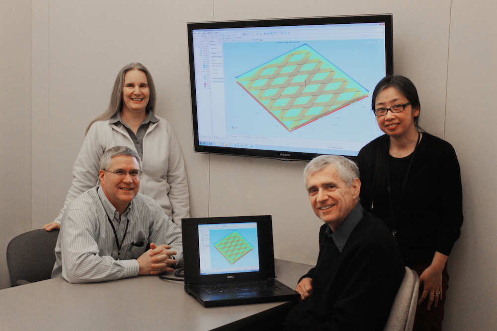
The research team at Boeing Research & Technology from left to right: Patrice Ackerman, Jeffrey Morgan, Robert Greegor, and Quynhgiao Le. Copyright © Boeing.
In their work, the researchers at BR&T have developed a coefficient of thermal expansion (CTE) model in COMSOL Multiphysics® simulation software. The figure shown above that presents the composite structure layup and EMF is a screenshot acquired from the model geometry used for their simulations in COMSOL Multiphysics.
The CTE model was used to evaluate heating of the aircraft composite structure as experienced upon descent, where the final and initial temperatures used in the simulations represent the ground and altitude temperatures, respectively. The Thermal Stress interface, which couples heat transfer and solid mechanics, was used in the model to simulate thermal expansion and solve for the displacement throughout the structure.
The material properties of each layer in the surface protection scheme as well as of the composites are custom-defined in the CTE model. The relative values of the coefficient of thermal expansion, heat capacity, density, thermal conductivity, Young’s modulus, and Poisson’s ratio are presented in the chart below.
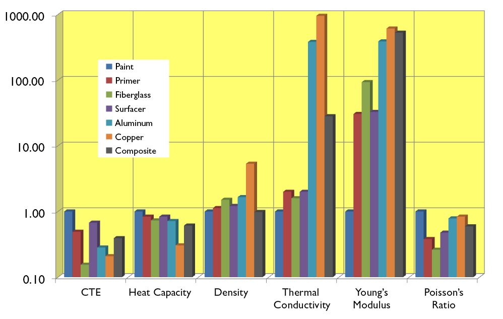
This graph presents the ratio of each material parameter relative to the paint layer. Copyright © Boeing.
From the graph, trends can be identified that provide early insight into the behavior of the materials, which aids in making design decisions. For example, the paint layer is characterized by higher values of CTE, heat capacity, and Poisson’s ratio, thus indicating that it will undergo compressive stress and tensile strain upon heating and cooling.
Multiphysics simulation takes this predictive design capability one big step forward by quantifying the resulting displacement due to thermal stress throughout the entire composite structure layup simultaneously, taking into account the properties of all materials. The following figure shows an example of BR&T’s simulation results and presents the stress distribution and displacement throughout the composite structure.
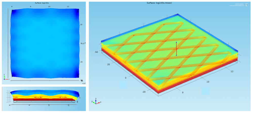
Left: Top-down and cross-sectional views of the von Mises stress and displacement in a one-inch square sample of a composite structure layup. Right: Transparency was used to show regions of higher stress, in red. Lower stress is shown in blue. Copyright © Boeing.
In the plots at the left above, the displacement pattern caused by the EMF is evident through the paint layer at the top of the composite structure while a magnified cross-sectional view shows the variations in displacement above the mesh and voids of the EMF. The cross section also makes it easy to see the stress distribution through the depth of the composite structure, where there is a trend toward lower stress in the topmost layers. Transparency was used in the plot shown at the right to depict the regions of high stress in the composites and EMF, which is noticeably higher at the intersection of the mesh wires. Stress was plotted through the depth of the composite structure layup along the vertical red line shown in the center of the plot. The figure below shows the relative stress in each layer of the composite structure layup for different metallic compositions of the EMF.
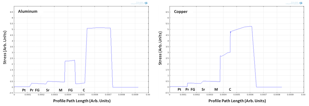
Relative stress in arbitrary units was plotted through the depth of the composite structure layups containing either aluminum (left) or copper EMF (right). Copyright © Boeing.
The samples vary by the presence of a fiberglass corrosion isolation layer when aluminum is used as the material for the EMF. The fiberglass acts as a buffer resulting in lower stress in the aluminum EMF, when compared with the copper.
Designing an EMF Layer for Reliable Lightning Strike Protection
From lightning strike protection to the structural integrity of the composite protection scheme, it all relies on the design of the expanded metal foil layer. The design of the EMF layer can vary by its metallic composition, height, width of the mesh wire, and the mesh aspect ratio. For any EMF design parameter, there is a trade-off between current-carrying capacity, displacement, and weight. By using the CTE model, the researchers at BR&T found that increasing the mesh width and decreasing the aspect ratio are better strategies for increasing the current-carrying capacity of the EMF that minimize its impact on displacement in the composite structure.
The metal chosen for the EMF can also have a significant effect on stress and displacement in the composite structure, which was investigated using simulation and physical testing. Two composite structures, one with aluminum and the other with copper EMF, underwent thermal cycling with prolonged exposure to moisture in an environmental test chamber. In the results, shown below, the protective layers remained intact for the composite structure with copper EMF. However, for the layup with aluminum, cracking occurred in the primer, at the edges, on surfaces, and was particularly substantial in the mesh overlap regions.
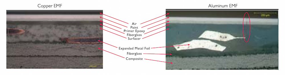
Photo micrographs of the composite structure layup after exposure to moisture and thermal cycling. A crack in the vicinity of the aluminum EMF is contained within the red ellipse. Copyright © Boeing.
Simulations confirm the experiment results. Shown below, displacements are noticeably higher throughout the composite structure layup when aluminum is used for the EMF layer, where higher displacements are associated with an increased risk for developing cracks. The higher displacement is easiest to observe in the bottom plots, which show displacement ratios for each EMF height.
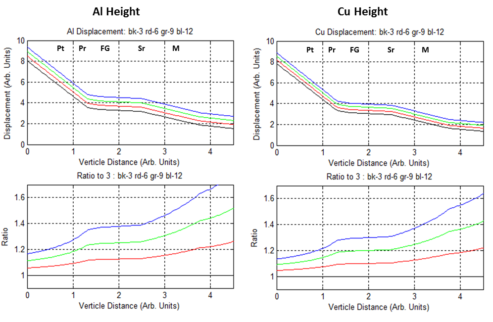
Effect of varying the EMF height on displacement in each layer of the surface protection scheme. Copyright © Boeing.
The larger displacements caused by the aluminum EMF can be attributed in part to its higher CTE when compared with copper, which exemplifies how important the properties of materials are to the thermal stability of the aircraft composite structures.
In the early design stages and along with experimental testing, multiphysics simulation offers a reliable means to evaluate the relative impact of the EMF design parameters on stress and displacement throughout the composite structures. An optimized EMF design is essential to minimizing the risk of crack formation in the composite surface protection scheme, which reduces maintenance costs and allows the EMF to perform its important protective function of mitigating lightning strike damage.
Further Reading
Refer to page 4 of COMSOL News 2014 to read the original article, “Boeing Simulates Thermal Expansion in Composites with Expanded Metal Foil for Lightning Strike Protection of Aircraft Structures”.
This article was based on the following publicly available resources from Boeing:
- The Boeing Company. “787 Advanced Composite Design.” 2008-2013.
- J.D. Morgan, R.B. Greegor, P.K. Ackerman, Q.N. Le, “Thermal Simulation and Testing of Expanded Metal Foils Used for Lightning Protection of Composite Aircraft Structures,” SAE Int. J. Aerosp. 6(2):371-377, 2013, doi:10.4271/2013-01-2132.
- R.B. Greegor, J.D. Morgan, Q.N. Le, P.K. Ackerman, “Finite Element Modeling and Testing of Expanded Metal Foils Used for Lightning Protection of Composite Aircraft Structures,” Proceedings of 2013 ICOLSE Conference; Seattle, WA, September 18-20, 2013.
To learn more about adding material property data to your COMSOL Multiphysics® simulations, read the following blog post series on Obtaining Material Data for Structural Mechanics Simulations from Measurements by my colleague Henrik Sönnerlind:
General information about aircraft design and structures can be found in chapter 1 of this handbook on aircraft maintenance from the Federal Aviation Administration.
BOEING, Dreamliner, and 787 Dreamliner are registered trademarks of The Boeing Company Corporation in the U.S. and other countries.

Comments (0)