AC/DC Module Updates
For users of the AC/DC Module, COMSOL Multiphysics® version 6.0 brings enhanced motor modeling support, fully coupled induction heating in layered materials, and frequency domain support for the Magnetic Fields, Currents Only interface. Learn about these updates and more below.
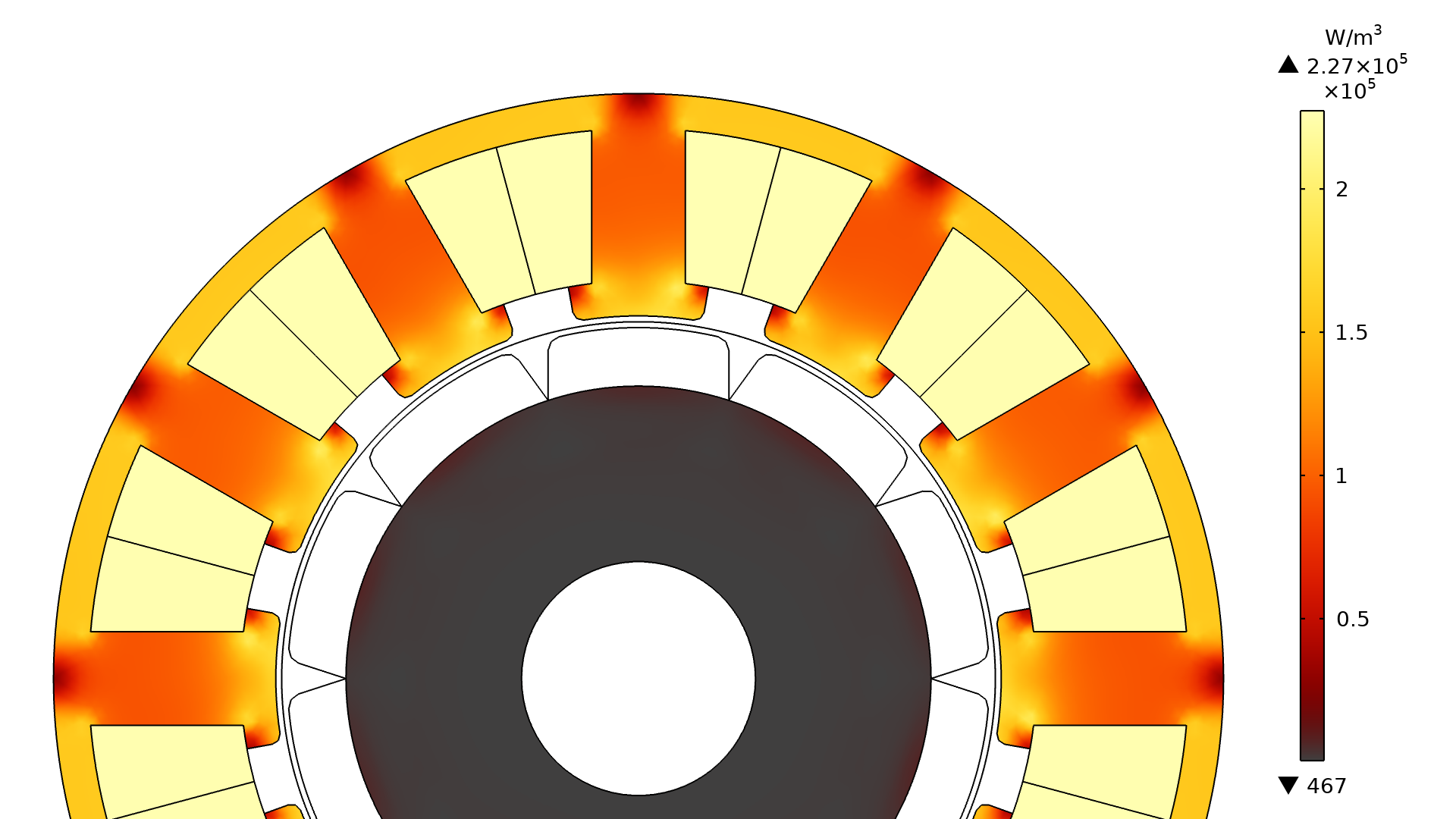
Arkkio Torque Calculation for the Rotating Machinery, Magnetic Interface
Rotating machines typically have a cylindrical air gap between rotor and stator, where electromagnetic fields are exchanged and forces and torque are exerted. The new Arkkio Torque Calculation feature in the Rotating Machinery, Magnetic interface analyzes the fields in this gap and makes it possible to easily evaluate the total torque exerted on the rotor and stator in both 2D and 3D. Also, several postprocessing quantities important for motor design are now available. These include the radial force density, azimuthal force density, radial magnetic flux density, and azimuthal magnetic flux density in the air gap. The Arkkio Torque Calculation feature requires the AC/DC Module and is demonstrated in the following tutorial models:
A synchronous motor with a three-phase winding on the stator and surface-mounted permanent magnets on the rotor.
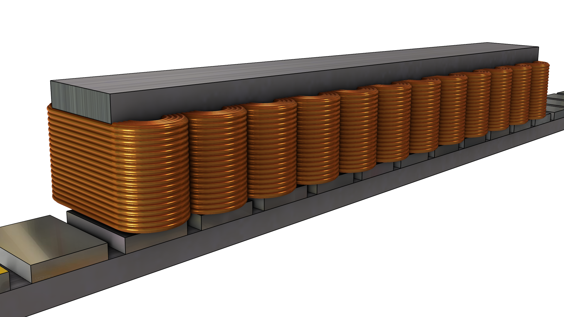
Periodic Pair for the Magnetic Fields Interface
The new Periodic Pair feature in the Magnetic Fields interface simplifies the modeling of linear machines in 2D (machines such as motors, generators, actuators, and sensors). Instead of modeling the entire device, periodicity is assumed: Typically one or a couple of unit cells are included, ignoring the end effects. This feature requires the AC/DC Module and is demonstrated in the new Linear Motor in 2D tutorial model.
A synchronous linear motor with a three-phase winding on the stationary part and permanent magnets on the moving part.
Magnetomechanics Multiphysics Interfaces
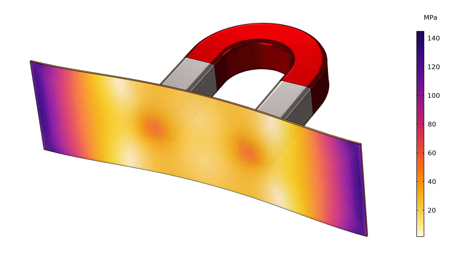
Two new physics interfaces for analysis of coupled magnetic and mechanical effects have been added: Magnetomechanics and Magnetomechanics, No Currents. When you add such an interface, two physics interfaces are added to the model: Solid Mechanics and either Magnetic Fields or Magnetic Fields, No Currents. The new Magnetomechanical Forces multiphysics coupling is also added. These interfaces can be found under the Electromagnetics and Mechanics branch in the Add Physics tree. You can view this functionality in the new Deformation of an Iron Plate by Magnetic Force tutorial model.
Note that in addition to the AC/DC Module, these interfaces require either the MEMS Module, Structural Mechanics Module, or Acoustics Module.
The dynamic behavior of an AC contactor. An AC contactor is a particular kind of switch that is activated by a coil carrying an AC current.
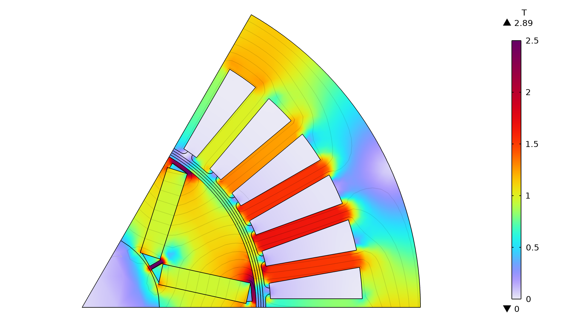
Magnetostriction for the Rotating Machinery, Magnetic Interface
Magnetostrictive materials exhibit free strain under the influence of a magnetic field. This is the effect causing the low-pitched humming sound coming from a transformer, for instance. While previously only available for the Solid Mechanics and Magnetic Fields interfaces, the Magnetostriction multiphysics coupling can now also be used to connect the Solid Mechanics and Rotating Machinery, Magnetic physics interfaces. It is available in 3D, 2D, and 2D axisymmetry. Magnetostriction is demonstrated in the existing Nonlinear Magnetostrictive Transducer tutorial model.
Note that in addition to the AC/DC Module, this multiphysics coupling requires either the MEMS Module, Structural Mechanics Module, or Acoustics Module.
The stator of a synchronous permanent magnet motor deforms due to magnetostriction (cogging forces are excluded, and displacements are not to scale).
Frequency Domain Support for the Magnetic Fields, Currents Only Interface
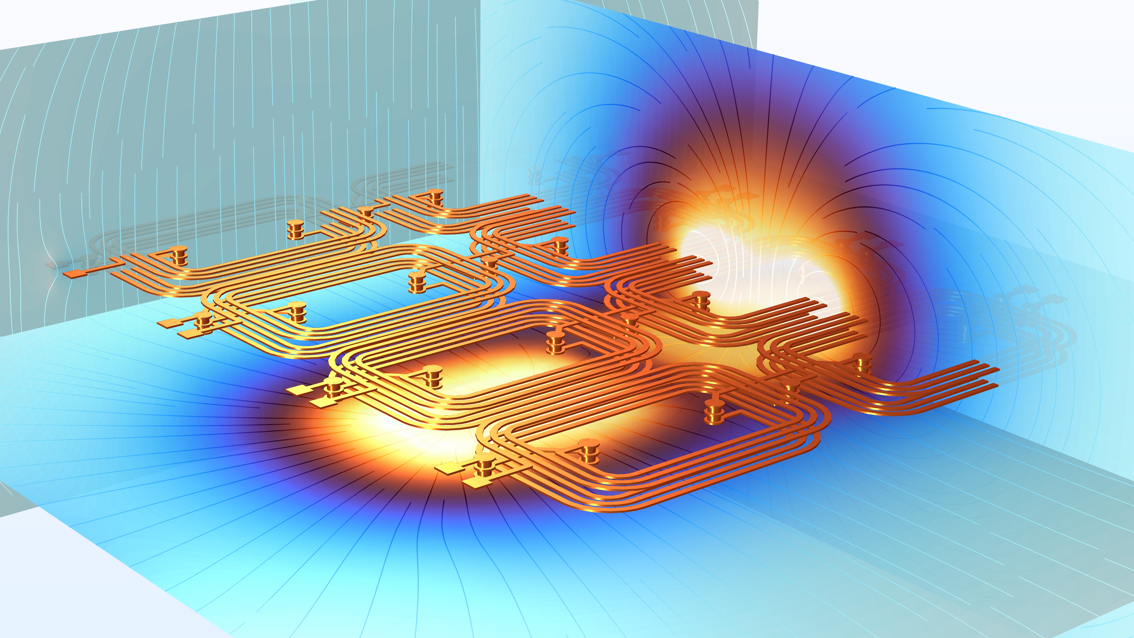
The Magnetic Fields, Currents Only interface, designed to efficiently compute lumped inductance matrices and resistance matrices of complex circuits in 3D, has now been extended to include frequency domain support. This is done using the new Frequency Domain Source Sweep with Initialization study step. It can be used to calculate the partial contributions from magnetic fields generated by open conductors, such as those commonly found on printed circuit boards (PCBs). This study step is demonstrated in the existing Inductance Matrix Calculation of PCB Coils tutorial model.
The main difference compared to the Stationary Source Sweep, introduced in COMSOL Multiphysics® version 5.6, is that the frequency-domain solution considers skin and proximity effects. This makes it possible to extract inductance matrices at low to medium frequencies (in the range where capacitive effects are not yet dominant). Also, the automated postprocessing for resistance and inductance matrices has been significantly improved. Note that the Magnetic Fields, Currents Only interface and its study types require the AC/DC Module.
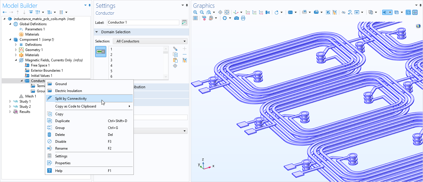
Split by Connectivity Option for Terminals, Conductors, and the Lumped Port
The new Split by Connectivity option is available in the context menu for Terminal nodes in, for example, the Electrostatics and the Magnetic and Electric Fields interface; for Conductor nodes in the Magnetic Fields, Currents Only interface; and for the Lumped Port in the Magnetic Fields interface.
This option is useful when a model contains many electrically conducting domains, some of them in contact, and some of them insulated from the rest. This situation is common for PCBs or touchscreens. When extracting resistance, inductance, and capacitance matrices for such a device, you typically want to take each individual "conductor" (or each insular part of the selection containing all conducting domains), assign a Terminal or Port feature to each of them, and then perform a sweep. With this new functionality, you can add a single Terminal feature to your model, have a single selection containing all conductors, and then choose Split by Connectivity to automatically generate a separate Terminal feature for each individual conductor. This will greatly speed up your workflow.
This functionality requires the AC/DC Module and is demonstrated in the Inductance Matrix Calculation of PCB Coils and Modeling a Capacitive Position Sensor Using FEM tutorial models.
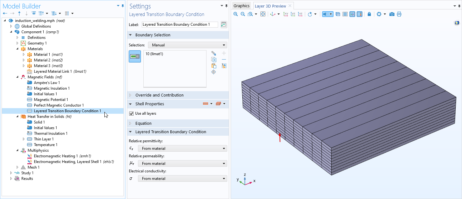
Layered Transition Boundary Condition for the Magnetic Fields Interface
At low to medium frequencies, the new Layered Transition Boundary Condition in the Magnetic Fields interface can be used to model composite electromagnetic shielding materials such as those containing mu-metal and copper layers or, for instance, gold-plated copper on a circuit board. At higher frequencies, this feature can even be used for modeling RF metamaterials and antireflection coatings, although for those applications, you would typically use the corresponding feature in the RF Module or the Wave Optics Module. The feature is used in combination with a Layered Material in the global Materials node, and a Layered Material Link in the Materials node. Together with the extended Electromagnetic Heating, Layered Shell multiphysics coupling, the Layered Transition Boundary Condition supports fully coupled induction heating in the layer stack. Note that the Layered Transition Boundary Condition feature requires the AC/DC Module.
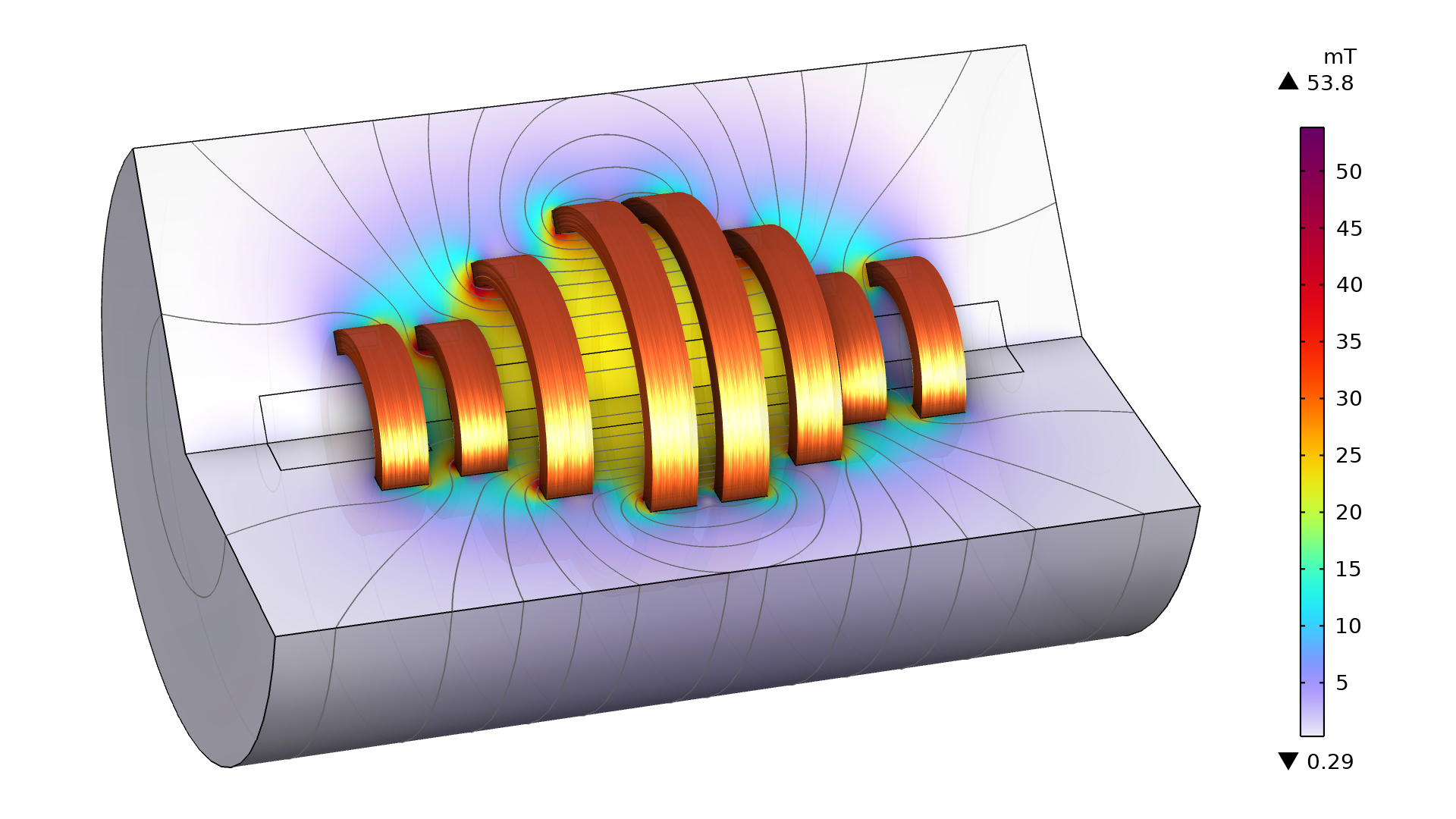
Fully Coupled Electromagnetic Heating for the Layered Transition Boundary Condition
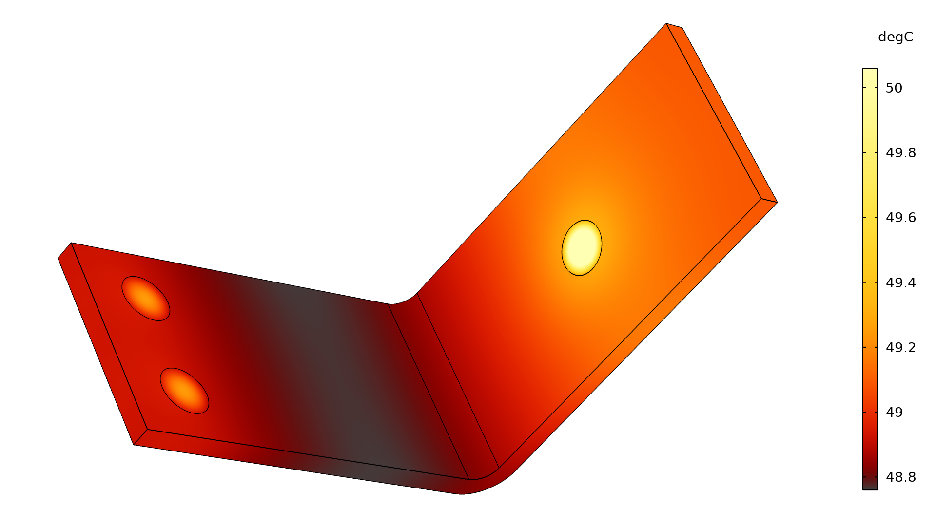
The Electromagnetic Heating, Layered Shell multiphysics coupling has been extended to support the Layered Transition Boundary Condition in the Magnetic Fields interface for frequency-stationary and frequency-transient study types in 2D and 3D. The Layered Transition Boundary Condition takes the layer-averaged, potentially temperature-dependent, material properties for each individual layer and uses them to compute the electromagnetic field propagation and power dissipation in the layer stack. The layer-averaged heat sources are then fed back into the thermal simulation. Together with the Thin Layer feature in the Heat Transfer in Solids interface, this allows you to investigate the temperature distribution in the layer stack. Typical use cases include the induction welding of layered composite materials, for example. Note that the Electromagnetic Heating, Layered Shell multiphysics coupling requires either the Heat Transfer Module or the AC/DC Module.
A film containing metallic and polymer layers is subjected to an external electromagnetic field. The induced currents cause the layered material to heat up.
Symmetry Plane Features for Various Interfaces
The new Symmetry Plane feature is available for the following physics interfaces: Electrostatics, Electric Currents, Magnetic Fields, and Magnetic Fields, No Currents. The symmetry planes for Electrostatics and Electric Currents provide symmetry and antisymmetry conditions for the electric field. For the Magnetic Fields and Magnetic Fields, No Currents interfaces, the symmetry type can be set for the magnetic flux density B and the magnetic field H, respectively. You can see this new feature in several tutorial models, including:
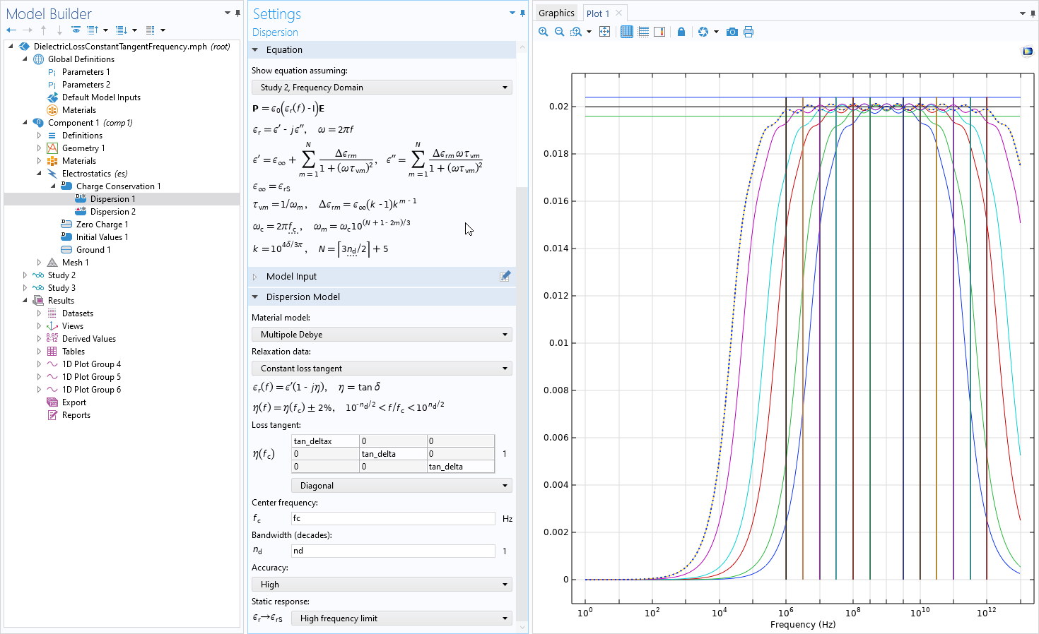
Debye Dispersion Models for Dielectrics
New damping models have been added for dielectric materials. Under Charge Conservation, when the material type is set to Solid, you can now use the Dispersion dielectric material model. In the Dispersion subnode, you can choose between the Debye and Multipole Debye dispersion models. This functionality is available for frequency-domain and time-dependent analysis. Note that this material model requires the AC/DC Module or the MEMS Module.
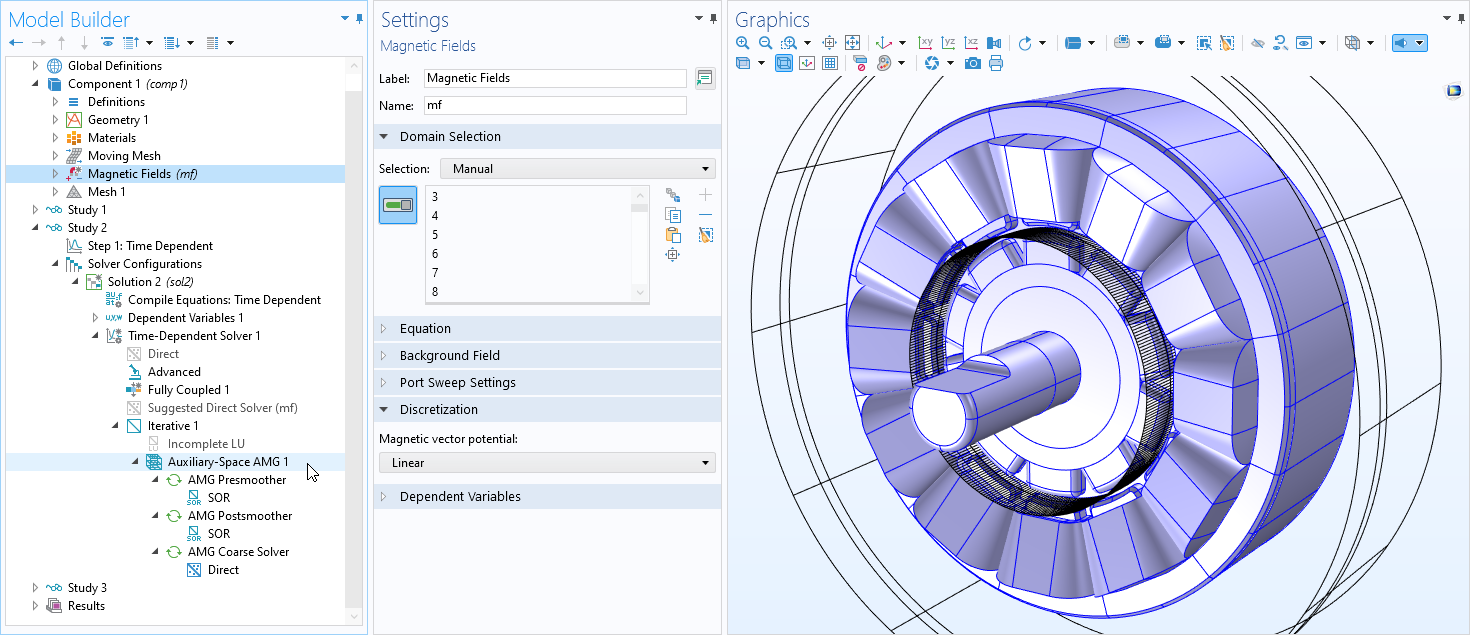
New Algebraic Multigrid Preconditioner for Linear Curl Elements
The Auxiliary-Space Algebraic Multigrid (ASAMG) preconditioner is an implementation of the Auxiliary-Space Maxwell (AMS) solver. For the AC/DC Module, it is now available as an alternative preconfigured solver in the default solver configuration for the Magnetic Fields interface. It is available when the discretization of that interface is set to Linear in 3D. Note that in 3D, the Magnetic Fields interface requires the AC/DC Module.
Geometry Part Library for Electric Motors
A new Geometry Part Library has been added specifically for modeling rotating machines in 2D. It contains three internal permanent magnet rotors and one external stator, equipped with coils. The rotor designs are fully parametric and include the following types: embedded magnet, embedded magnet (V-shape configuration), and surface-mounted magnet. These geometry parts are used in the following tutorial models:
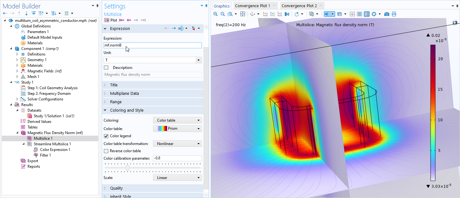
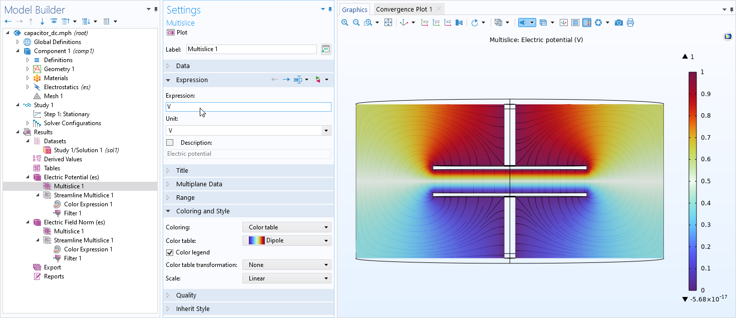
Improved Plot Defaults
As an extension to the default plot improvements included in COMSOL Multiphysics® version 5.6, the plot defaults in the AC/DC Module now use new color tables and new plot features such as the Streamline Multislice plot. A new Prism color table has been designed specifically for vector field norms with singular tendencies such as the electric field norm or the magnetic flux density norm. Multislice and streamline plots are combined to indicate both field strength and direction. For physics interfaces that use a scalar potential formulation — Electrostatics, Electric Currents, Magnetic and Electric Fields, and Magnetic Fields, No Currents — extra plot groups are added that use the symmetric Dipole color table.
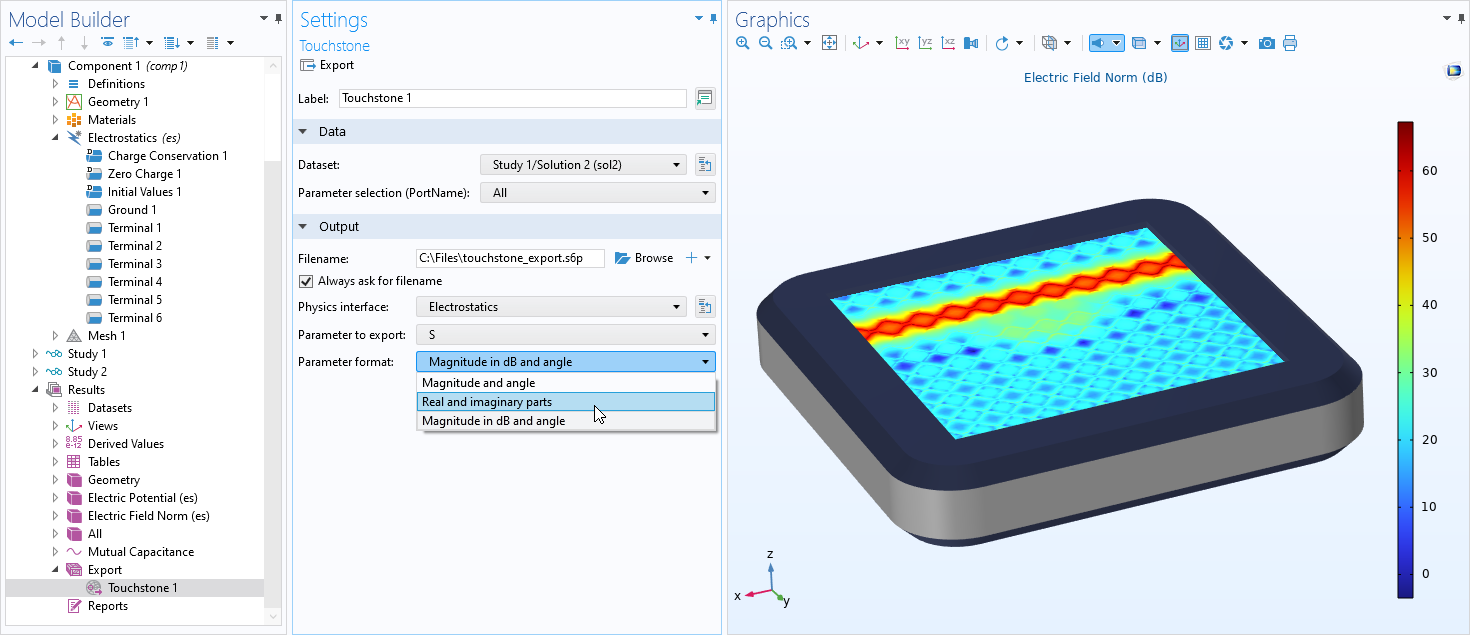
Touchstone Export Support in Postprocessing
The Electrostatics, Electric Currents, and Magnetic Fields interfaces can generate S-parameter matrices through port or terminal sweeps. In addition to the old Touchstone export functionality in previous versions of the software, these physics interfaces now support the Touchstone export functionality available during postprocessing.
Electric Circuit Improvements
The Electric Circuit interface has received a number of fixes and extensions. These improvements include the support for importing and exporting the mutual inductance SPICE element K and more robust and general SPICE import. Note that this interface is supported by many products including the AC/DC, MEMS, Plasma, RF, Semiconductor, and Battery Design modules.
New Tutorial Models
COMSOL Multiphysics® version 6.0 brings several new tutorial models to the AC/DC Module.
Linear Motor in 2D
Application Library Title:
linear_motor_2d
Download from the Application Gallery
Permanent Magnet Motor in 2D
Application Library Title:
pm_motor_2d_introduction
Download from the Application Gallery
Parameter Optimization of an Electric Motor
Application Library Title:
electric_motor_parameter_optimization
Download from the Application Gallery
Shape Optimization of Coils
Application Library Title:
coil_shape_optimization
Download from the Application Gallery
Deformation of an Iron Plate by Magnetic Force
Application Library Title:
plate_deflected_by_magnet
Download from the Application Gallery
Electrical Heating in a Busbar with Terminals
Application Library Title:
busbar_terminal
Download from the Application Gallery