

Vacuum is naturally associated with the hostile environment of deep space. To achieve such an environment in an artificial setting here on Earth is a very challenging task, and it turns out one cannot even come close to the low pressures of an interstellar vacuum. It is at these low pressures that molecular flow occurs.
Many High-Tech Applications Require Vacuum Technology
Where can we find applications that require a vacuum on Earth? For one, manufacturing of computer chips wouldn’t be possible without vacuum-based processes. Turns out, there are actually quite a few high-tech applications where vacuum technology is critical or beneficial. These include mass spectrometers, molecular beam equipment for doping of semiconductors, chemical vapor deposition for thin optical coatings, electron microscopy, particle accelerators, and satellites. There are, of course, also more “everyday vacuum” applications such as that of a thermos bottle’s insulating layer or an incandescent light bulb.
For high-tech vacuum applications, engineers use a range of specialized high-vacuum pumps to pull out air molecules from a tightly enclosed vacuum chamber.

Typical vacuum chamber in a research lab.
Engineering Problems with Vacuum Systems
Now, to get a high vacuum you cannot just pump for a while and then shut the pump off. Your pumps need to be running all the time. Why? Gas molecules have a way of seeping into the chamber in a number of different ways, and more molecules means increased pressure — and then the vacuum is destroyed. So where do these gas molecules come from? One source could be that the chamber is not perfectly sealed. In that case, you get gas molecules into your chamber from the fact that almost all materials naturally release gas molecules to its surroundings. For instance, the very metal and glass materials that make up your vacuum chamber might be the culprit in destroying the vacuum (not so much an issue for high-end systems).
Additionally, sealants, adhesives, and lubricants are releasing a lot of molecules. You probably know the smell of rubber; that smell comes from released gas molecules, and if you have a smelly rubber material in a vacuum chamber it will destroy your vacuum. The phenomena of unwanted molecules being released into your vacuum system is called outgassing and is one of the most challenging engineering aspects of vacuum technology: you need to pick the right materials that don’t release so many molecules. Take your chamber walls for example. You cannot use just any steel; it has to be stainless steel. The list of nonpermissible materials is long. Some spectacular cases of outgassing problems have involved deep-space probes, such as the Stardust comet sample return probe where condensation of an unwanted substance on the camera sensor reduced image quality.
Another fascinating engineering problem with vacuum systems is that when you open your chamber up for servicing your equipment, water vapor will get in. The water vapor has a tendency of condensing on the walls as water and then slowly releasing water molecules into the chamber. Engineers then bake the vacuum system overnight by heating the system up so that the water evaporates and can be pumped out.
Once the achieved pressure is obtained, the chamber can be used for its technical application purpose, like doping of a semiconductor material using an ion beam. An ion beam is too fragile to be directly sent through air — the ions will collide with the air molecules and be dispersed, so a high-quality vacuum is necessary. Precisely what quality vacuum is needed depends on the application, but this table will give you an idea:
| Application | Molecules per cm3 (approximate) |
|---|---|
| Atmospheric air | 1019 |
| Light bulb | 1015 |
| Thermos | 1013 |
| High-tech vacuum chamber | 106 |
| Interstellar space | 10 |
Rarefied Flow Simulation Tools for Complex Vacuum Systems
To understand and engineer a complex vacuum system, the rarefied flow simulation tools of the COMSOL® software can be used. Rarefied gas flow occurs when the mean free path of the molecules becomes comparable with the length scale of the flow. The size of your equipment, in other words. The mean free path of a gas molecule is simply how far it travels, on average, before hitting another gas molecule. To quantify this, you can compute the Knudsen number, which gives you a quick indication of what type of flow you’re looking at. The Knudsen number, Kn, is the mean free path divided by a typical length scale. Let’s look at the four flow regimes characterized by the Knudsen number:
- Continuum flow (Kn < 0.01)
- Slip flow (0.01 < Kn < 0.1)
- Transitional flow (0.1 < Kn <10)
- Free molecular flow (Kn > 10)
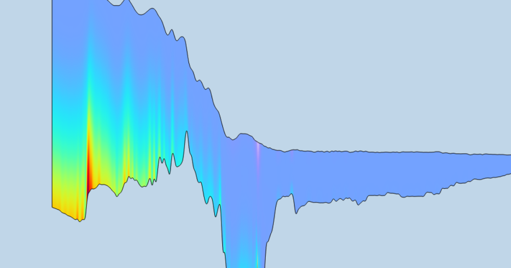
These flow regimes are shown in the figure below:

A plot showing the main fluid flow regimes for rarefied gas flows. Different regimes are separated by lines of constant Knudsen numbers. The number density of the gas is normalized to the number density of an ideal gas at a pressure of 1 atmosphere and a temperature of 0°C (n0).
Free Molecular Flow Regime
Typical vacuum systems will feature gas pressures well within the Free Molecular Flow regime. The COMSOL® software also has tools for the transitional, slip, and (of course) continuum flow, but let’s leave that topic for a future blog post. If you examine the above Knudsen number plot closely you will notice that if a gas has a more “normal” pressure than that of a vacuum system but is confined to flow in a very narrow channel, say nanometer sized, then the flow is also in the free molecular flow region. This means that to investigate gas flow through porous materials where the pores are very narrow, so called nano-pores, you will also need free molecular flow simulation capabilities. One such application area is shale gas exploration.
With the dedicated Free Molecular Flow simulation tools you can, for example, compute the number of molecules per unit volume at each point in your system. You can then examine the number density along the intended trajectory of an ion beam and decide if the vacuum system needs to be changed in any way to lower the number density. In the Free Molecular Flow regime, the molecules are traveling along straight lines, bouncing randomly against the walls of the vacuum system. This means that the flow of molecules behaves similarly to light beams and that you can engineer the geometric configuration of your system to achieve shadowing effects and exploit those to lower the number density. Indeed, the numerical algorithm used for free molecular flow in COMSOL Multiphysics® has many things in common with that of infrared radiation, or heat radiation, computations. It is, however, a tad bit more advanced in order to accurately represent the flow.
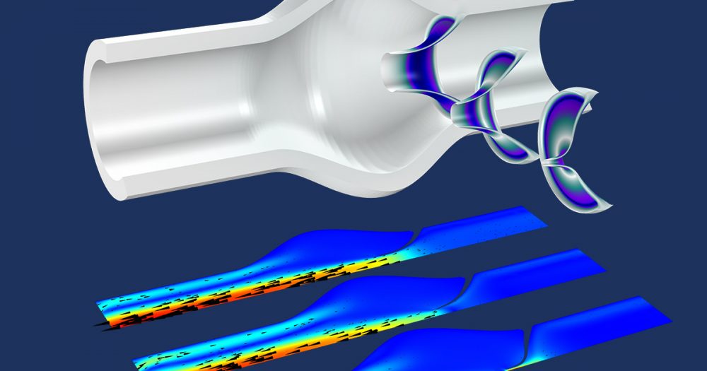
For a practical example of a molecular flow calculation, see this model tutorial of an ion implanter.

Simulation of a semiconductor ion implanter to minimize the pressure along the ion beam path using the COMSOL® software. The plot shows the pressure on the surfaces of the vacuum system; two walls have been removed so that the inside of the chamber is visible.

Comments (2)
Molika Linkolnli
January 9, 2019Dear Bjorn,
Do it work on liquid flow?
for example, water flow in (nano) porous media.
Thanks,
Daniel Smith
January 9, 2019Hi Molika, this is for gases only and does not apply to liquids flowing through very small scale structures.
Dan