
In mid to late 2020, hotly anticipated 5G-enabled smartphones began to roll out to the general public. One of the key aspects of the new 5G infrastructure that supports these devices is RF filters. These filters, which are used to stop signal interference, can become subject to significant temperature variations resulting in structural deformation, especially in extreme environmental conditions. Engineers designing RF filters for 5G devices must be able to analyze how temperature variations and thermal stresses affect their performance. This is where multiphysics simulation comes into play.
What Is an RF Cavity?
There are many RF and microwave applications that feature RF cavities, including radar, microwave ovens, and (as we’ll discuss a bit later) cellphone stations. They are also found in particle accelerators, such as the Large Hadron Collider (LHC) at the European Organization for Nuclear Research (CERN), which includes 16 RF cavities. Particle accelerators use RF cavities to accelerate charged particles by giving them an electrical impulse when they are injected into the cavity.
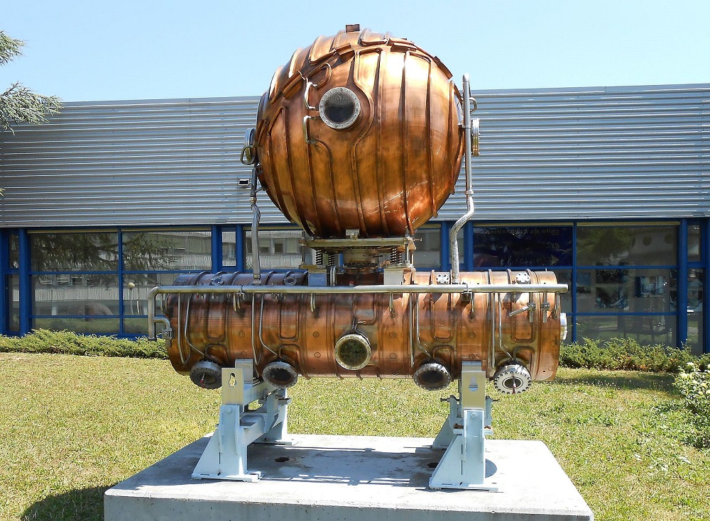
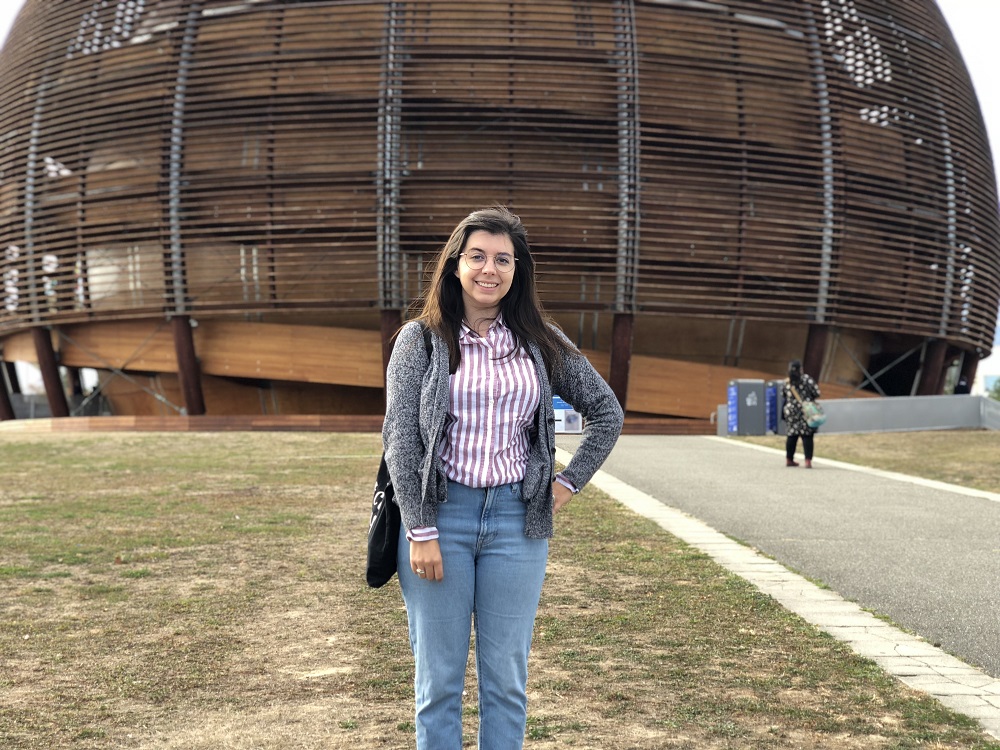
At left, an RF cavity from a particle accelerator at CERN. Image by MarsPF2 — Own work. Licensed under CC BY-SA 3.0, via Wikimedia Commons. At right, the blog author at a visit to CERN in 2018.
Cavity Filters for 5G Devices
Smartphones and other 5G devices need to be able to transmit and receive signals from a wide variety of sources. They require multiple frequency bands that can operate simultaneously through a single antenna, a multiple-input, multiple-output (MIMO) system. Filters are used to select the desired signals from a specific frequency band and reject the unwanted frequency components, which can interfere with performance. 5G network infrastructure operates in newer and higher frequency bands than ever before, ranging from several GHz to tens of GHz, further exacerbating the need for optimized filter devices.
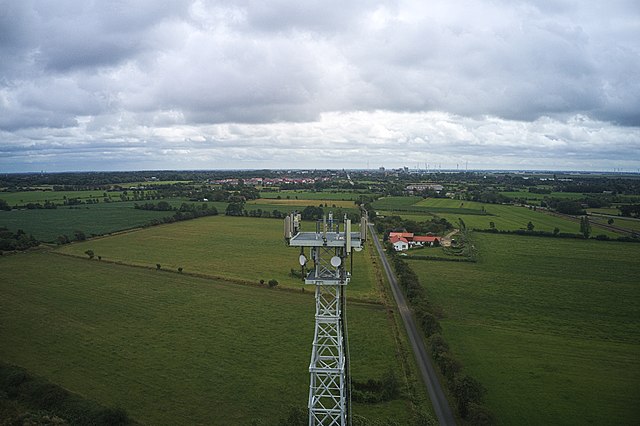
A 5G tower near Hattstedt, Germany. Image by Fabian Horst — Own work. Licensed under CC BY-SA 4.0, via Wikimedia Commons.
Because 5G is a worldwide network, 5G structures and devices exist in areas that experience extreme environmental conditions, like sudden changes in temperature. Variations in temperature can cause expansion and structural deformation of RF filters, affecting their performance, for example, in terms of their S-parameters.
Thermal analysis and stress deformation are important considerations for filter designs, but they are often left out of the conventional electromagnetics-driven design approach for this type of device. Laboratory experiments also tend to neglect these effects. What’s an engineer to do?
RF, Thermal, and Stress Analysis of a Cavity Filter in COMSOL Multiphysics®
In the Thermostructural Effects on a Cavity Filter tutorial model, we demonstrate how multiphysics simulation can be used to analyze the resonant frequencies of a cavity filter design.
Cavity filters are typically made out of both dielectric and metallic materials. The conductivity of metals varies with temperature, which affects the losses in the device and dissipates heat. The dissipation of heat leads to a rise in temperature, and a variation in temperature will cause materials to expand or contract. Thus, when a cavity filter undergoes a high power load or an extreme thermal environment, drift may occur, which makes it challenging to design such filters.
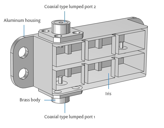
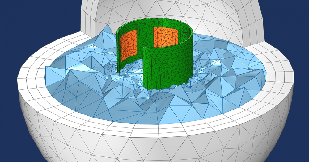
Model geometry for the cavity filter.
The tutorial model discussed here includes three separate studies. First, you can perform a frequency-domain study of a cascaded cavity filter that covers two common wave bands for 5G communications:
- 26.5–29.5 GHz, used for 5G bands in Japan, Korea, and the United States
- 24.25–27.5 GHz, used for 5G bands in the European Union and China
Next, you can analyze the thermal deformation of the filter device with a prescribed uniform temperature distribution, as well as its impact on the filter performance. This part of the study investigates the filter in two different scenarios:
- Different (but uniform) ambient temperatures
- A temperature variation (nonuniform) across the device (for example, when a nearby component overheats)
The latter part of the tutorial shows how you can compute a nonuniform temperature distribution in the model, instead of using an imposed, fixed uniform temperature deviation, for a more accurate representation of the real-world scenario.
Modeling Assumptions
Before getting into the tutorial, let’s go over some of the key modeling features within each of the physics.
- Electromagnetics
- Impedance boundary condition (IBC) used instead of modeling the conducting walls as volumes
- Temperature-dependent conductivity of the metallic coating inside the cavity
- A coaxial-type lumped port with the terminal type as cable is used as a source
- Structural mechanics
- Rigid boundary used at the ports to allow motion and rotation, but not deformation
- Spring foundation used as an approximate an adhesive bonding to a rigid plate
- Moving Mesh is used to define the deformation of the air domain within the cavity
- Heat transfer
- Heat Flux boundary condition used to give a linearly varying (along the x direction) temperature source (for the nonuniform heat source)
Frequency-Domain Study
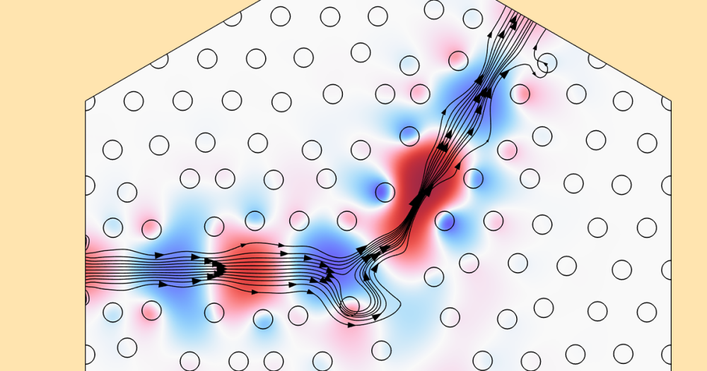
The results of the model show the electric field norm and S-parameters for the two 5G frequency bands under normal operating conditions, which you can then use to compare with the models that include thermal stress and structural deformation. The field pattern indicates the presence of TE101 mode inside the cavity.
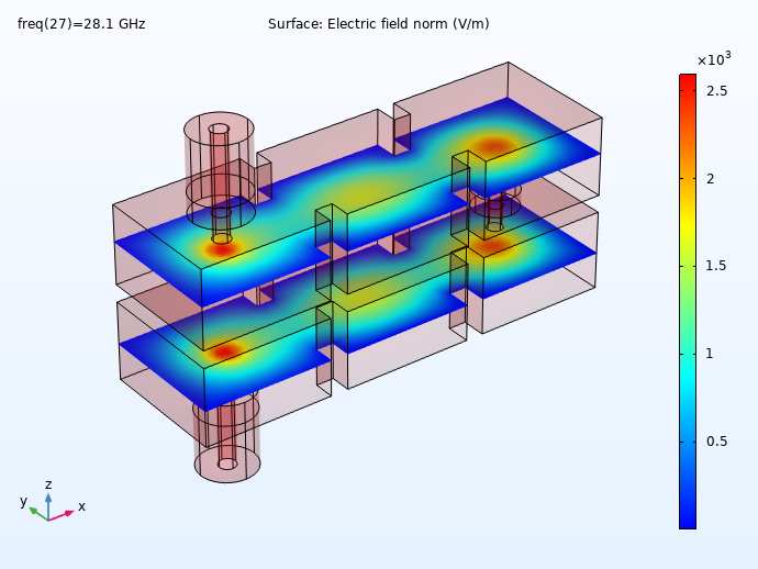
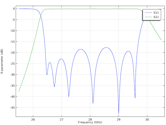
Electric field norm (left) and S-parameter plot (right) for the 5G bands in Japan, Korea, and the U.S.
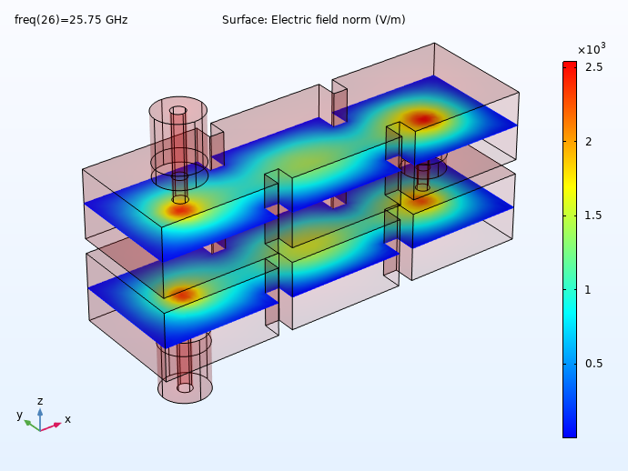
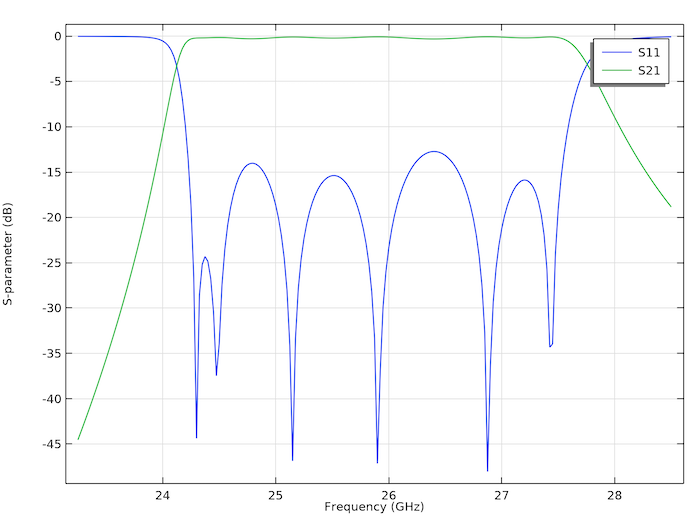
Electric field norm (left) and S-parameter plot (right) for the 5G bands in the E.U. and China.
Thermostructural Analysis
The coupled thermostructural analysis shows that both the uniform and uneven heat source on the filter’s baseplate results in structural deformations.
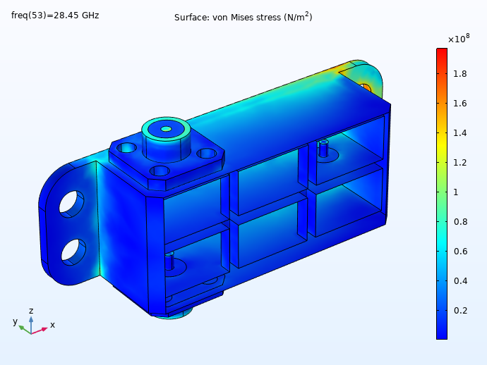
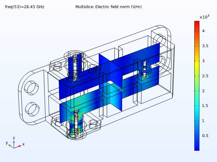
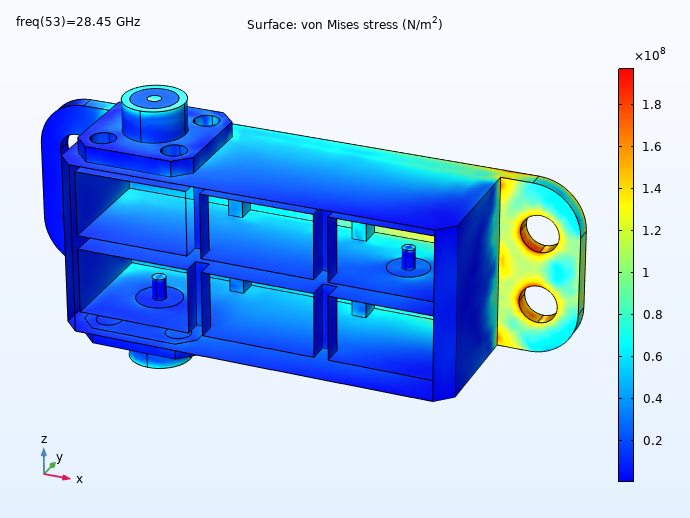
Left: Thermal stresses in the cavity filter at 100 K above the initial temperature. Right: Electric field norm at the last frequency out of the passband (input signal does not reach output port). These figures are for the uniform heat source.
The results suggest that although the resonant frequencies are affected by deformation and thermal stress, the S-parameters are not significantly distorted thus validating the design.
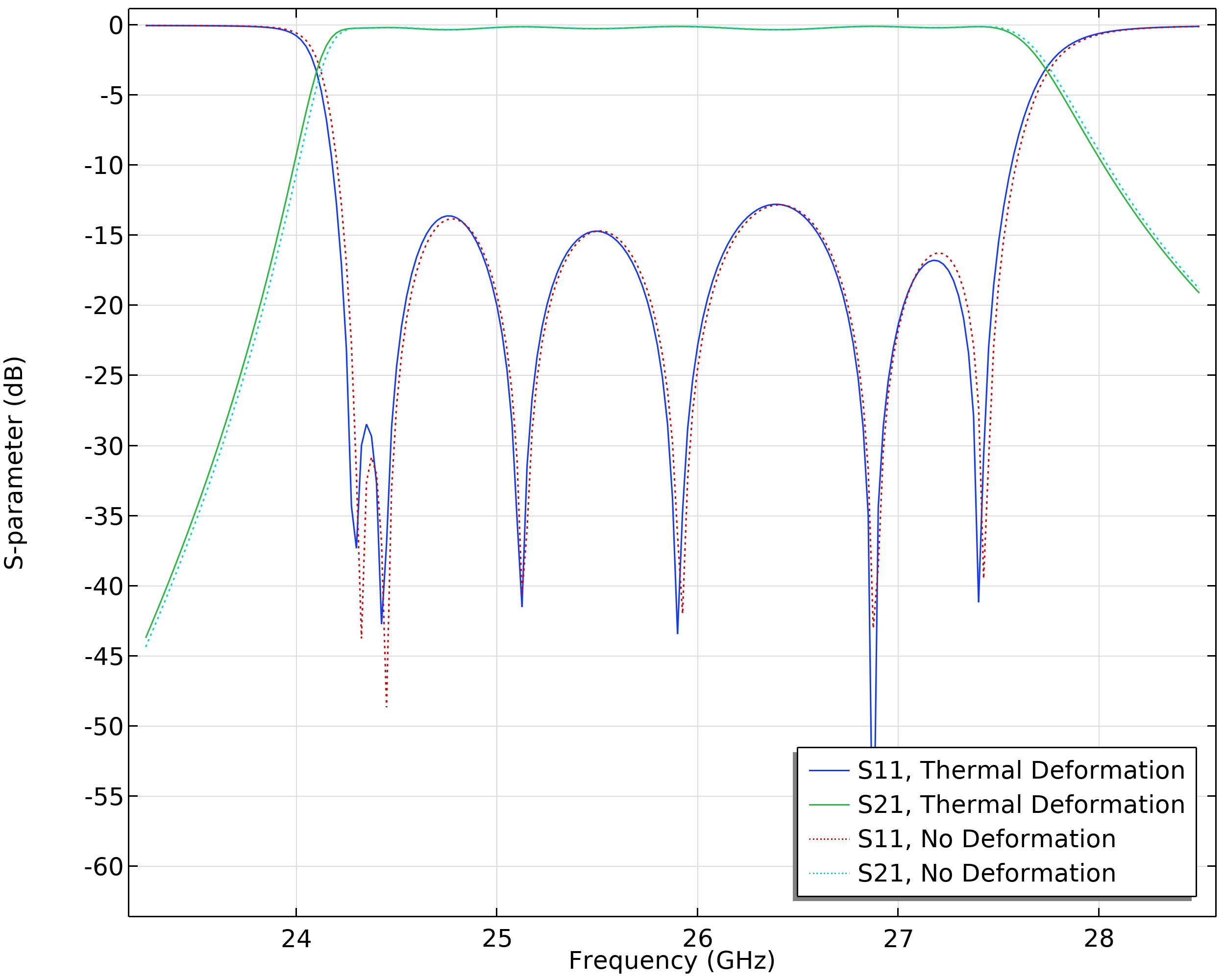
Left: Slight shift in S-parameters due to baseplate deformation. Right: Structural deformation in the aluminum housing of the cavity filter due to thermal expansion. These figures are for the uneven heat source.
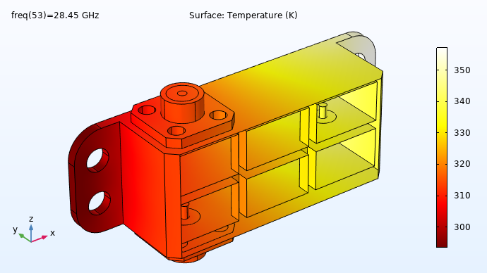
Surface plot of the temperature. The plot shows which areas of the aluminum housing and coaxial connectors get hotter.
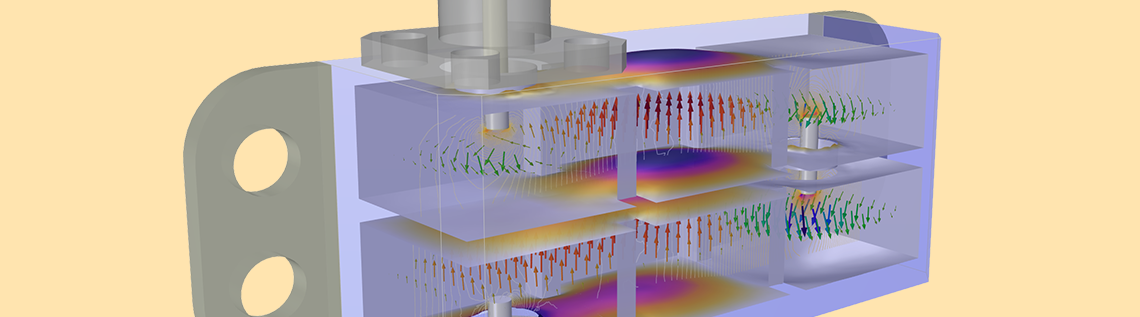
The fully coupled analysis of the cavity filter device, shown below, also demonstrates the Partial Transparency postprocessing feature available as of COMSOL Multiphysics version 5.6.
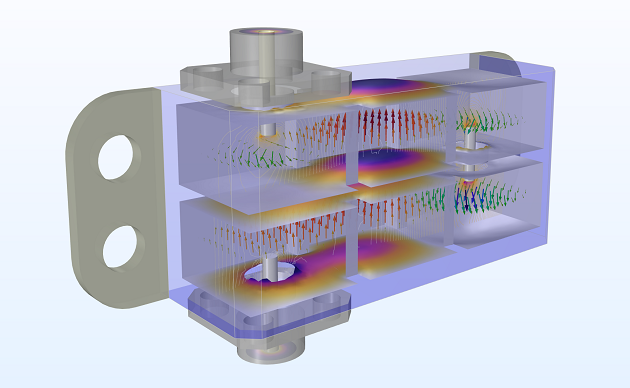
By performing a coupled analysis of the electromagnetic, structural, and thermal effects in a 5G cavity filter, we can determine how the performance of the filter is affected by thermostructural phenomena. In this case, we get the positive result that the thermally induced structural deformation does not affect the electrical performance noticeably.
Next Steps
Try it yourself: Get the Thermostructural Effects on a Cavity Filter tutorial model by clicking the button below.

Comments (0)